PicoScope 7 Automotive
Available for Windows, Mac, and Linux, the next evolution of our diagnostic scope software is now available.
Automotive guided tests
Library of examples on how to perform tests when using PicoScope.

Training
Our collection of training videos, articles, guides and information on training courses.

Waveform library
The Waveform Library is a global database of waveforms uploaded by PicoScope users.

Case studies
Real-life case studies show how the professionals use PicoScope to diagnose vehicle faults.

A to Z of PicoScope
Detailed description of various PicoScope software and hardware features.

Videos
Training resources and demonstrations on PicoScope and the Automotive Diagnostics Kit.

Newsletter
Archive of our monthly Automotive Newsletters.

Documentation
Download manuals, brochures, posters, and training materials.

Reviews and awards
Accolades for the preferred diagnostic tool for service centers and vehicle manufacturers.


WPS500X Pressure Transducer
*At Pico we are always looking to improve our products. The tool used in this guided test may have been superseded and the product above is our latest version used to diagnose the fault documented in this case study.
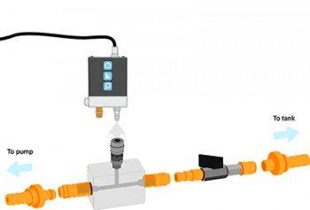
The purpose of this test is to verify the integrity of the high-pressure transfer pump or feed pump, internal leaks on the high-pressure side, fuel filter blockage, pipes and hoses for leaks, injector leaks and any aeration within the fuel system.
Before starting the test ensure WPS500X is fully charged.
Always remember when dealing with fuel to observe health and safety conditions at all times.
When starting the vehicle please bear in mind the safety aspect of high-pressure systems. Although we are checking the low-pressure side, if there are leaks on the HP side this could result in serious injury or fatality.
|
Refer to vehicle technical data for specific test conditions and results.
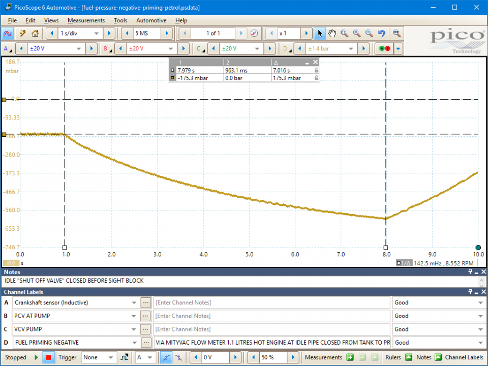
After re-priming the fuel circuit we should now see a negative pressure on the screen. This indicates the transfer pump is drawing fuel in but more importantly fuel is remaining primed in the circuit. If there were concerns with hoses or the internals of the pump, especially if there were no external leaks evident, we would most likely see this negative pressure return to atmospheric as the circuit is unable to keep the fuel primed.
From the waveform we can see that the initial draw from the transfer pump is good measure at -175.3 mBar (3). We can quickly put maximum load on the pump by shutting off the stop tap and monitor the efficiency of the pump before it stops the engine (4) pulling around -600 mBar. We can also monitor how quickly the pump recovers when we reopen the tap, again proving the efficiency of the pump. What we do need to bear in mind is the fuel filter and any blockages in the pipework. If there is a blockage the initial negative pressure will be lower than that we have seen on the above waveform.
For a more in depth analysis you could couple this low pressure test with a high pressure test utilising the common rail pressure sensor. This would allow you to monitor flow of fuel to the pump and rise time, plus monitoring any drop in pressure from the rail pressure sensor and the sight block which could indicate a potential leak on either the HP side or the LP side. Bear in mind though the ignition would need to be left on to allow the rail pressure sensor to remain active should you wish to observe rail pressure drop over time.
GT833
Disclaimer
This help topic is subject to changes without notification. The information within is carefully checked and considered to be correct. This information is an example of our investigations and findings and is not a definitive procedure.
Pico Technology accepts no responsibility for inaccuracies. Each vehicle may be different and require unique test
settings.
We know that our PicoScope users are clever and creative and we’d love to receive your ideas for improvement on this test. Click the Add comment button to leave your feedback.
Ruzsa János (Autonet)
March 22 2018
Great test!
but please insert a warning at the beginning, to check if the HP pump does REALLY have internal transfer pump, and works through sucking the fuel, as by the other systems with electrical feed pumps the test will not work.
Most important is, that by Bosch CP4 systems opening the low pressure line introduces air in the system, which will cause a FATAL damage of the HP pump (by that systems low pressure side has ALWAYS to be bleeded with the diagnostic tool).


