PicoScope 7 Automotive
Available for Windows, Mac, and Linux, the next evolution of our diagnostic scope software is now available.
Automotive guided tests
Library of examples on how to perform tests when using PicoScope.

Training
Our collection of training videos, articles, guides and information on training courses.

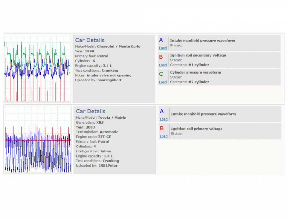
Waveform library
The Waveform Library is a global database of waveforms uploaded by PicoScope users.

Case studies
Real-life case studies show how the professionals use PicoScope to diagnose vehicle faults.

A to Z of PicoScope
Detailed description of various PicoScope software and hardware features.

Videos
Training resources and demonstrations on PicoScope and the Automotive Diagnostics Kit.

Newsletter
Archive of our monthly Automotive Newsletters.

Documentation
Download manuals, brochures, posters, and training materials.

Reviews and awards
Accolades for the preferred diagnostic tool for service centers and vehicle manufacturers.


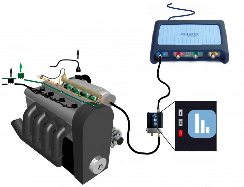
Universal vacuum adaptor

Vacuum hose
*At Pico we are always looking to improve our products. The tools used in this guided test may have been superseded and the products above are our latest versions used to diagnose the fault documented in this case study.
The purpose of this test is to evaluate the intake manifold pressures of a naturally aspirated gasoline engine during cranking conditions using the WPS500X pressure transducer.
Note
Some Engine Control Modules (ECMs) operate the throttle independently to the accelerator pedal position. This will alter your waveform. If this is the case, you will need to disconnect the throttle body connector and re-test.

This known good waveform has the following characteristics:
0 bar is expressed as a relative pressure and indicates atmospheric pressure.
The inlet manifold pressure is initially at 0 bar (atmospheric pressure) with the engine stationary.
The pressure drops below 0 bar once the engine has started to crank and an induction stroke has created the necessary conditions.
A series of negative pulses, depressions, occur as the engine continues to crank.
The depression amplitudes and frequencies increase as the engine speed increases.
During steady-state cranking, the peak depression amplitude is around -65 mbar and the intake manifold pressure consistently remains below 0 bar.
The inlet manifold pressure returns to 0 bar at the end of cranking.
A positive pressure peak, reaching around 40 mbar, and then a negative peak, immediately follow.
The inlet manifold pressure returns to 0 bar.
Go to the drop-down menu bar at the lower left corner of the Waveform Library window and select Intake manifold pressure waveform.
An internal combustion engine acts as an air pump. It draws air in through the intake and forces it out through the exhaust. The rate at which the air mass enters the intake is the rate at which the air mass leaves the exhaust (unless it is added to or expelled via other means, such as leaks).
Air mass flow depends on engine speed, engine displacement, and intake manifold air density. Within the intake manifold volume, the air density depends on pressure. Therefore, if we use a throttle valve to regulate the intake manifold pressure, we can control the intake air density.
If engine speeds and throttle valve positions are known, we can use intake manifold pressure measurements to evaluate the air mass flow behaviour within an engine.
Please note: you should only make pressure value decisions based on comparison with manufacturer data.
Waveform features
Intake manifold pressure behaviour, during cranking, can be described, as follows:
Waveform diagnosis
The intake manifold pressure reflects the net effect of all cylinder and intake interactions. The relationships are complex; for example, two valve-overlap scenarios occur around the start of every induction stroke:
Although a uniform pattern should be apparent, the intake manifold pressure waveform characteristics cannot be accurately predicted without exact knowledge of the engine design.
Therefore, diagnosis relies mostly on the identification of periodic anomalies within the waveform. An observed anomaly provides sufficient justification for further investigation.
We can link typical faults to possible waveform effects, for example:
GT426-EN
Disclaimer
This help topic is subject to changes without notification. The information within is carefully checked and considered to be correct. This information is an example of our investigations and findings and is not a definitive procedure.
Pico Technology accepts no responsibility for inaccuracies. Each vehicle may be different and require unique test
settings.
We know that our PicoScope users are clever and creative and we’d love to receive your ideas for improvement on this test. Click the Add comment button to leave your feedback.


