PicoScope 7 Automotive
Available for Windows, Mac, and Linux, the next evolution of our diagnostic scope software is now available.
Automotive guided tests
Library of examples on how to perform tests when using PicoScope.

Training
Our collection of training videos, articles, guides and information on training courses.

Waveform library
The Waveform Library is a global database of waveforms uploaded by PicoScope users.

Case studies
Real-life case studies show how the professionals use PicoScope to diagnose vehicle faults.

A to Z of PicoScope
Detailed description of various PicoScope software and hardware features.

Videos
Training resources and demonstrations on PicoScope and the Automotive Diagnostics Kit.

Newsletter
Archive of our monthly Automotive Newsletters.

Documentation
Download manuals, brochures, posters, and training materials.

Reviews and awards
Accolades for the preferred diagnostic tool for service centers and vehicle manufacturers.


20 A / 60 A DC (low amps) current clamp
*At Pico we are always looking to improve our products. The tool used in this guided test may have been superseded and the product above is our latest version used to diagnose the fault documented in this case study.
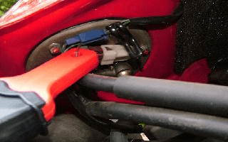
Plug the BNC moulded plug of the low-amp current clamp into Channel A of the scope. If the motorbike has a single fuse for the fuel pump, it may be possible to remove the fuse and use an extension fuse test lead to connect the current clamp. On our test bike the fuel and ignition systems share a common fuse and, although it is not recommended, we have had to release the fuel tank securing bolts to gain access to the pump's wiring, as in Figure 1. Extreme care should be taken to support the tank whilst the securing bolts are removed.
With the example waveform displayed on the screen you can now hit the space bar to start looking at live readings.

The normal operating pressure within this system is approximately 2 bar (30 psi) and at this pressure the current draw on the pump is 2 to 3 amps. The waveform should appear to be consistent with the 'peaks and troughs' being equal to one another.
This type of high-pressure fuel pump is called a roller cell pump, with the fuel entering the pump and being compressed by rotating cells which force it through the pump at a high pressure. The pump is capable of producing a higher pressure than the operating pressure and has a delivery rate of approximately 3 to 4 litres per minute. Within the pump is a pressure relief valve that lifts off its seat at a predetermined pressure. The pressure relief valve is there to arrest the pressure if a blockage in the filter or fuel lines or other problems cause it to become obstructed. The other end of the pump (output) is home to a non-return valve which, when the voltage to the pump is removed, closes the return to the tank and maintains pressure within the system.
Most fuel pumps fitted to today's motorcycles are fitted within the petrol tank and are referred to as 'submerged' fuel pumps. The pump is often located with the fuel gauge sender unit (when fitted).
Mounted vertically, the pump comprises inner and outer gear assemblies that together are called the 'gerotor'. The combined assembly is secured in the tank using a series of screws and sealed with a rubber gasket, or with a bayonet-type locking ring. Fuel passing across the fuel pump's armature will be subjected to sparks and arcing, which sounds dangerous, but the absence of oxygen means that there will not be an explosion!
The waveform in the illustration shows the current for each sector of the commutator. The majority of fuel pumps have 6 to 8 sectors and a repetitive point on the waveform can indicate wear and an impending failure. In the illustration a lower current draw can be seen on one sector and this is repeated when the pump has rotated through 720°. This example has 8 sectors per rotation.
Not applicable.
AT112-2
Disclaimer
This help topic is subject to changes without notification. The information within is carefully checked and considered to be correct. This information is an example of our investigations and findings and is not a definitive procedure.
Pico Technology accepts no responsibility for inaccuracies. Each vehicle may be different and require unique test
settings.
We know that our PicoScope users are clever and creative and we’d love to receive your ideas for improvement on this test. Click the Add comment button to leave your feedback.


