PicoScope 7 Automotive
Available for Windows, Mac, and Linux, the next evolution of our diagnostic scope software is now available.
Automotive guided tests
Library of examples on how to perform tests when using PicoScope.

Training
Our collection of training videos, articles, guides and information on training courses.

Waveform library
The Waveform Library is a global database of waveforms uploaded by PicoScope users.

Case studies
Real-life case studies show how the professionals use PicoScope to diagnose vehicle faults.

A to Z of PicoScope
Detailed description of various PicoScope software and hardware features.

Videos
Training resources and demonstrations on PicoScope and the Automotive Diagnostics Kit.

Newsletter
Archive of our monthly Automotive Newsletters.

Documentation
Download manuals, brochures, posters, and training materials.

Reviews and awards
Accolades for the preferred diagnostic tool for service centers and vehicle manufacturers.


20 A / 60 A DC (low amps) current clamp

Multimeter Probes
*At Pico we are always looking to improve our products. The tools used in this guided test may have been superseded and the products above are our latest versions used to diagnose the fault documented in this case study.
The purpose of this test is to monitor the current draw from an injector whilst observing the primary ignition trace.
WARNING
This test involves measuring a potentially hazardous voltage.
Please ensure you follow manufacturers' safety instructions and working practices and ensure the rated voltage for all accessories you are using meets or exceeds the expected voltage.
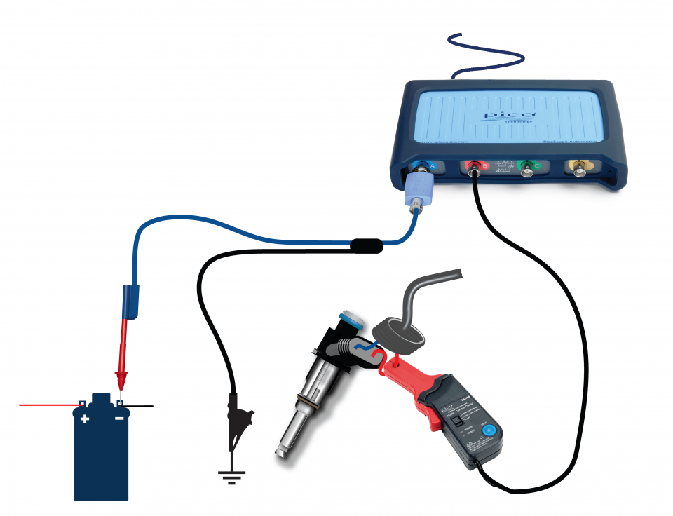
View connection guidance notes.
Note
This helpfile refers to a 10:1 attenuator. If you are using a 20:1 attenuator please adjust the Probe settings for the relevant channel. These settings can be found under the Channel Options button, then: Probe > 20:1 Attenuator.
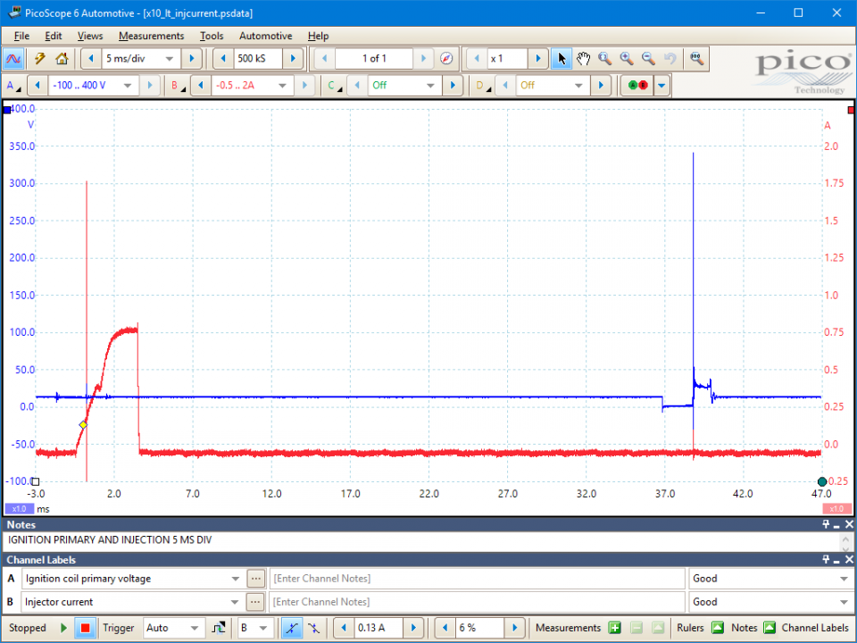
In this waveform we can observe the current drawn by the injector (shown in red) at the same time as monitoring the primary ignition trace (shown in blue).


The main reason for evaluating these two waveforms together is to identify the cause of a non-start situation or sudden loss of power, causing the engine to stop.
If the primary trace is absent, there will be no switching of the injectors as these two circuits are timed together while the loss of the injector current signifies that a fault has occurred within the injection circuit.
The frequency of the injection trace when compared to the primary signal will differ between sequential and simultaneous injection. Sequential having one pulse per 720, while simultaneous will predominantly have two. Some simultaneous systems do however have a single pulse, but these are in the minority.
GT391
Disclaimer
This help topic is subject to changes without notification. The information within is carefully checked and considered to be correct. This information is an example of our investigations and findings and is not a definitive procedure.
Pico Technology accepts no responsibility for inaccuracies. Each vehicle may be different and require unique test
settings.
We know that our PicoScope users are clever and creative and we’d love to receive your ideas for improvement on this test. Click the Add comment button to leave your feedback.
gamesellru
May 16 2021
It seems to me it is very good idea. Completely with you I will agree.


