PicoScope 7 Automotive
Available for Windows, Mac, and Linux, the next evolution of our diagnostic scope software is now available.
Automotive guided tests
Library of examples on how to perform tests when using PicoScope.

Training
Our collection of training videos, articles, guides and information on training courses.

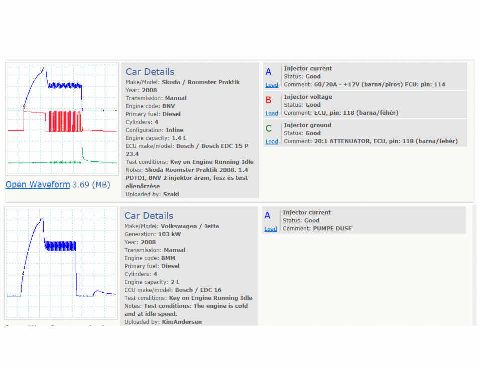
Waveform library
The Waveform Library is a global database of waveforms uploaded by PicoScope users.

Case studies
Real-life case studies show how the professionals use PicoScope to diagnose vehicle faults.

A to Z of PicoScope
Detailed description of various PicoScope software and hardware features.

Videos
Training resources and demonstrations on PicoScope and the Automotive Diagnostics Kit.

Newsletter
Archive of our monthly Automotive Newsletters.

Documentation
Download manuals, brochures, posters, and training materials.

Reviews and awards
Accolades for the preferred diagnostic tool for service centers and vehicle manufacturers.


20 A / 60 A DC (low amps) current clamp

Multimeter Probes
*At Pico we are always looking to improve our products. The tools used in this guided test may have been superseded and the products above are our latest versions used to diagnose the fault documented in this case study.
The purpose of this test is to examine the electrical operation of a VAG PD injector, current, voltage and earth circuits.
WARNING
This test involves measuring a potentially hazardous voltage.
Please ensure you follow manufacturers' safety instructions and working practices and ensure the rated voltage for all accessories you are using meets or exceeds the expected voltage.
To avoid possible damage to your scope, you may need to use an attenuator for this test.
Scopes with a 200 V range, such as PicoScope 4x25 models, do not need an attenuator for this test.
All other PicoScope Automotive models need an attenuator on the channel input. You can use either a 10:1 or a 20:1 attenuator provided that you adjust the PicoScope software accordingly. Select from the appropriate Channel Options menu:
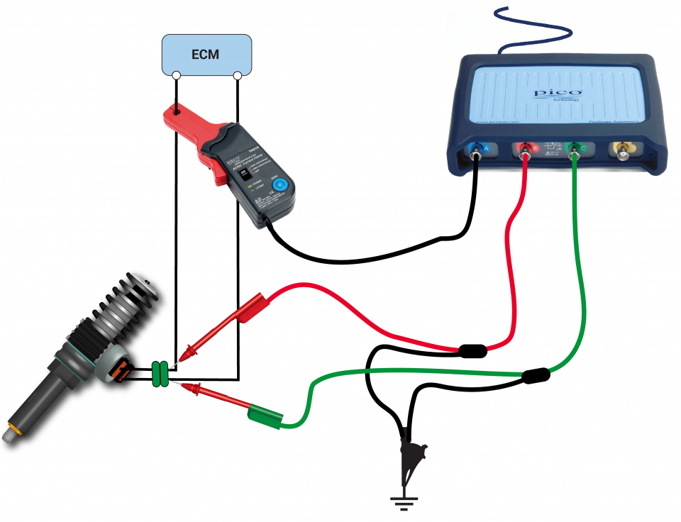
View connection guidance notes.
Do not electrically disconnect a piezoelectric injector with the engine running. Ensure secure diagnostic electrical connections are made.
Note
The orientation of the current clamp relative to the wire will determine whether it has a positive or negative output. If a live waveform does not appear on your screen, or appears to be inverted, try reversing the orientation of the clamp.
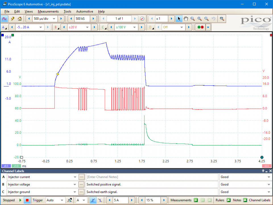
This shows the injector current. At the point of injection the current rises from zero to around 15 amps where there is a brief interruption before continuing to rise to just over 17.5 amps. The injection current remains high for a short period before reducing to about 11 amps and then enters a multi-pulsing phase.
This shows the injector live circuit. It is important to note that the injectors are live switched; at the start point of injection the normal battery supply voltage is shown at around 14 V. The supply voltage is modulated to create the injection phases throughout the injector duration of around 2 ms.
This shows the injector earth circuit. At the end of the injection period the voltage in the injector's electromagnetic windings collapses and this induced voltage can be seen rising to around 50 volts.
Go to the drop-down menu bar at the lower left corner of the Waveform Library window and select, injector current.
You can refine your search by selecting, make VW.

The electromechanical unit injectors are located inside the cylinder head, and the wiring runs through a circular multi-plug at the rear of the head to the individual injectors. The injectors are unlike common-rail injectors in that the high fuel pressure is generated by an additional rocker-arm running from the camshaft and acting directly on the injectors to compress the fuel, so there is no high-pressure pump. This action generates between 1,800 and 2,050 bar of pressure.
This system is referred to by the Volkswagen Audi Group as Pumpe-Düse (PD).
The electrical control also differs from common-rail as the supply voltage is at normal battery voltage. The switching of the injections is conducted by the positive supply and not by controlling the earth path.
As with all modern injectors there is a pilot and main injection phase to control noise and emissions and maintain a smooth combustion. The rise of the injector current from zero to the maximum is the pilot injector period. The period of the multi-pulsing current is the main injection phase.
Selection of component related Diagnostic Trouble Codes (DTCs)
P0251 - Injection Pump Fuel Metering Control "A" Malfunction (Cam/Rotor/Injector)
P0252 - Injection Pump Fuel Metering Control "A" Range/Performance (Cam/Rotor/Injector)
P0253 - Injection Pump Fuel Metering Control "A" Low (Cam/Rotor/Injector)
P0254 - Injection Pump Fuel Metering Control "A" High (Cam/Rotor/Injector)
P0255 - Injection Pump Fuel Metering Control "A" Intermittent (Cam/Rotor/Injector)
P0256 - Injection Pump Fuel Metering Control "B" Malfunction (Cam/Rotor/Injector)
P0257 - Injection Pump Fuel Metering Control "B" Range/Performance (Cam/Rotor/Injector)
P0258 - Injection Pump Fuel Metering Control "B" Low (Cam/Rotor/Injector)
P0259 - Injection Pump Fuel Metering Control "B" High (Cam/Rotor/Injector)
P0260 - Injection Pump Fuel Metering Control "B" Intermittent (Cam/Rotor/Injector)
GT385
Disclaimer
This help topic is subject to changes without notification. The information within is carefully checked and considered to be correct. This information is an example of our investigations and findings and is not a definitive procedure.
Pico Technology accepts no responsibility for inaccuracies. Each vehicle may be different and require unique test
settings.
We know that our PicoScope users are clever and creative and we’d love to receive your ideas for improvement on this test. Click the Add comment button to leave your feedback.


