PicoScope 7 Automotive
Available for Windows, Mac, and Linux, the next evolution of our diagnostic scope software is now available.
Automotive guided tests
Library of examples on how to perform tests when using PicoScope.

Training
Our collection of training videos, articles, guides and information on training courses.

Waveform library
The Waveform Library is a global database of waveforms uploaded by PicoScope users.

Case studies
Real-life case studies show how the professionals use PicoScope to diagnose vehicle faults.

A to Z of PicoScope
Detailed description of various PicoScope software and hardware features.

Videos
Training resources and demonstrations on PicoScope and the Automotive Diagnostics Kit.

Newsletter
Archive of our monthly Automotive Newsletters.

Documentation
Download manuals, brochures, posters, and training materials.

Reviews and awards
Accolades for the preferred diagnostic tool for service centers and vehicle manufacturers.

| Vehicle details: | Vauxhall Corsa |
| Year: | 2004 |
| Symptom: | MIL on, Non-starter with cranking, P1615, P1616 |
| Author: | Nick Hibberd | Hibtech Auto-Electrical Diagnostics |
This 2004 Corsa 1.2 arrived with dash and engine auxiliaries already stripped and its trims and covers in the boot. In fact the ECM was missing and had to be sourced from the previous repairer; so a good start. The car had an original complaint of a sudden no-start condition after seemingly faultless running, the previous diagnosis had condemned the engine ECU and I was called for an independent opinion.
On arrival I found the engine would crank with good speed but wouldn’t fire. From previous dealings with this model I know the engine MIL and oil MIL are controlled by the ECM, and here I had the engine MIL flagged but no oil MIL: a possible early clue. Checking the system with the scan tool found P1615 WRONG VEHICLE ID FROM BODY CONTROLLER and P1616 WRONG VEHICLE ID FROM INSTRUMENT, with both faults logged as present and unable to clear. At this early stage there was no suggestion that I was dealing with the usual suspects: CKP, CMP, fuel delivery, or any base calculation sensor. This problem was leaning towards a CAN issue or an exchange of data between control units.
It’s helpful to gain some knowledge of the electrical architecture of the vehicle under test: where control units are located, their master/slave relationship, and the number of networks will prove a worthwhile research.
Here is the basic layout I found for the main control units.
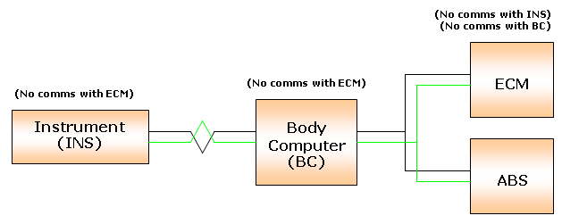
Already a bigger picture is emerging about the problem and the likely area to start looking. The ECM is reporting a problem with both INS and BC, yet data exchange between INS and BC themselves appears OK (no DTCs) making the ECM a common denominator. Both INS and BC appear to be functioning fine with all their associated auxiliaries working, so a power supply issue is unlikely. Also I have good communication between the scan tool and ECM, allowing different self-activations and accurate live parameter readings, so again a power supply issue at the ECM is unlikely. The next step is to verify the data transmission line: the CAN bus.
There’s no better place to take measurements than directly at the control unit. Why? You are seeing what the control unit sees. Fig.1 shows a typical recording taken from the two CAN cables at the ECM.
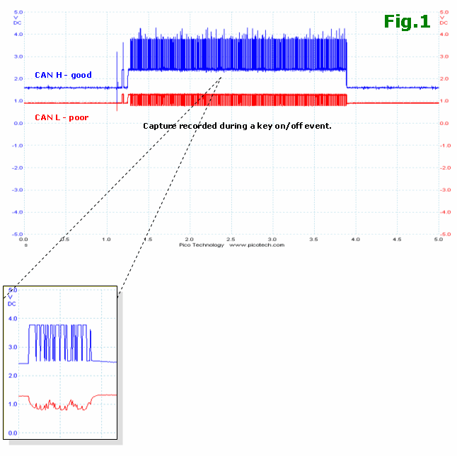
This is far from the pair of mirror-image signals we would normally expect to see. CAN H represents a good signal structure with well-defined dominant and recessive bits, but CAN L displays no recognisable bit transmission and its line stability has drifted low.
TIP: Expect some networks to revert to single-wire CAN if such a problem exists. However, this ECM remained off-line throughout.
CAN relies on differential transmission, where a recognisable message is achieved by the difference in voltage between the two lines. Ordinarily in this case a recessive bit would result in 0 V between two cables and a dominant bit would result in 2 V. With our problem car the erroneous CAN L will affect the overall data packet received.
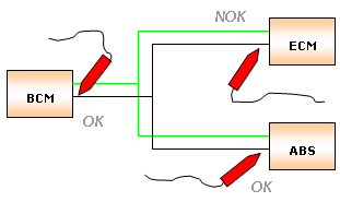
This is good confirmation that a CAN fault exists, so now we must try to isolate the problem. Each node was checked to monitor general line activity and make some comparisons. I found good CAN signal structure at the ABS and BCM, leaving only the ECM affected by the fault. This has localised the problem to engine bay area and focuses on the wiring between the ECM and its harness splice onto the CAN line.
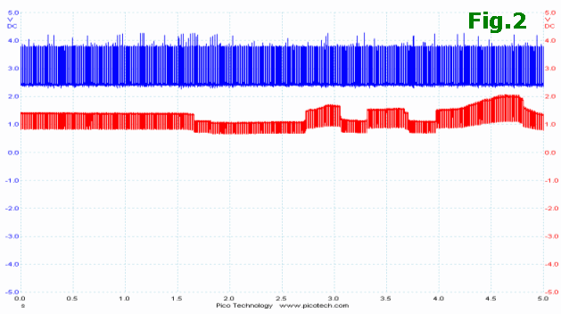
Fig.2 was recorded during a wiggle test on the engine harness and shows a direct effect on signal structure when the harness is flexed. At one point I managed to get the CAN lines close to normal, at which point the ECM eventually allowed a successful start for first time in a long while. Stripping the harness eventually revealed the fault.

A small section of the CAN cabling had suffered from corrosion badly and had eaten away nearly all of the cable strands. It is likely a result of chafing on the inside of its protective conduit which is supposed to protect the harness from such failure – ironically. Because the test points were intentionally placed at the rear of the control unit, positive confirmation of a problem was easy. Generally, taking CAN measurements at mid-harness connections or perhaps at a CARB socket is a valid circuit performance check; but just be aware that a spliced take-off with an open circuit will be near-invisible when you check the main line and its termination resistors.
Thinking back to the beginning, having the engine MIL flagged but no oil MIL is a peculiar system response to this CAN line fault but one worth remembering. Operational characteristics aren’t something read in a manual, but are learnt through hands-on experience. Hope it helps.
Stevie
May 30 2021
I’ve a similar non-start, 1.7cdti combo. flashing spanner, no start, no kline comms..however CN seems to scope fine. My CAN wiring seems to be a 2 core with outer black covering in the engine compartment. Not a bare exposed pair.
VOLKAN
June 23 2018
I’m having the same problem. This cable is at the exact location of the vehicle
Desmond Downs
July 20 2017
Very interesting, just had an Opel Vita in with intermittent starting fault and codes P1616. U2106 and U2107 so will start with scoping CAN lines.
k.henly
May 09 2017
great wright up but where are these wires located? i have the same problem with my corsa c i have looked for these wires but not sure where they are to.
Andrew Farmer
July 31 2016
Great article. Just had exactly the same fault and nailed it thanks to this. White CAN wire rubbed through where the protective tubing meets the hard plastic harness support. Soldered, heatshrunk, replicated the twists. Sorted!
Neil Corfield - Master Technician Trainer
January 07 2016
Great article here;
Clear indication of the CAN H & L Signals, can often prove without doubt the signal condition from each control unit.
In this case shown highlighted a broken wire.
I have also had identical fault codes in relation to water ingress within the ABS Control Unit and subsequently poor connection of the transmission lines to ECM, Body and Instrument Controls Modules.
I currently set this a diagnostic fault for students.
Claude
May 02 2015
Many thanks for your article on this problem. Had same issue with one car and after reading your article I found the cambus wire broken. After the repair the car started straight away.
chris
February 24 2015
hi i have an issue with my corsa c.my washer pump wont work and have replaced and replaced ignition switch,along with indicator arm.had Auto electrics out ,checked falts no falt shown,tested wires to washer pump and fuses althogh i told him had done.he said it may be the BODY CONTROL MODULE,BUT DIDUNT SHOW AS FALT ON DIEGNOSTICS ,FALT STILL PRESANT AND PAID AUTO ELECTRIC £60 POUND AND HE WAS PATHETIC ,DIDUNT FIX DAM WRONG.CAN ANY BODY HELP PLEASE OR SHOW ME HOW TO TEST PLEASE
Bogdan
October 10 2014
Great write up !
There is so much to be learned from this Cases !
I guess you are the last desperate solution where all other shops just fail !
Arvind
September 04 2014
I have code U0d00 and U1100 to do with Can bus comma error. Can someone please give information on location where this wire damage is?
Anonymous
September 03 2014
Help I have Corsa C 1.2l 2002 auto had U0D00, U1100. Can communication error codes. Where about people have the damaged wires? Please help.
Regards
Arvind
stuart
March 20 2014
same as above I am also looking for this broken wire, anyone have any idea?
Rob
February 01 2014
I have exactly the same fault with a corsa where was this wire found broken
Anonymous
November 25 2013
great way to explain how easy a diagnosys can be with a logical aproach and understanding of the system you are working on, thank you very much.
Jay
November 21 2013
Had the same fault code along with a worn through can bus wire, repaired wire now all good.
Gordon
February 28 2012
Where exactly was this wire broken? I have this exact same fault on my own Corsa C. Run fine Thursday night, Monday morning, runs for 2 seconds each time then dies.
Codes are wrong ID from BCM, wrong ID from Instrument Control Unit and occasional no communication with ABS.
bill
December 13 2011
brilliant diagnostic by logic and experiance.
a example of how it should be done
Mark
May 30 2011
Nice diag. Looks like CAN C, a little curious of which had the terminating resistors.
first transit/ MTS
mursal
March 27 2011
Thanks guys, very interesting
Fahim
December 04 2010
Thanks for the great write up! You sure know your stuff. Amazing! 😊
John Mazarakis Holden TAC
December 01 2009
Nice diagnosis….Excellent description.
KCA01
November 04 2009
Thanks so much for taking the time to share, great layout and explanation, very helpful - lesson learned 😊
KT CHUNG
June 17 2009
In this case I had understand test CAN bus skill.
Thank you very much
claude
June 11 2009
What i do not understand is how the scanner can communicates with the ecu if there is a CAN issue.the diagnostic plug is not integrated in the ecu, but in the harness i think.
Dave Smith
June 01 2009
I’m glad people have the time to document repairs like this as it is so helpful and reasuring that these problem can (no pun intended) be solved with the right knowledge and a logical approach.
A. Bothwell
May 30 2009
This kind of stuff really seperates the men from the boys in Auto Electrical, excellent example of quality testing to achieve the right diagnosis.
R.Westenskow
May 30 2009
Thank you Nick for another fine diagnostic example.
In your above waveforms are you probing with “low-pass filters”??
when you probe CAN signals?
paul robbie
May 30 2009
Great reading,my only question is was there any evidence why this corrosion started? Was there any evidence of a previous repair or water ingress into the harness?
d jones
May 30 2009
Another good example of “to fix it you must be able to see it”. Thanks for the insight.
Jerry
May 29 2009
I think it is good diagnostics I just took a class on can communications and I was impressed with Pico.
Nick Tillyer
May 29 2009
Again, another very useful and informative real world scenario great for professionals and students alike. Thanks for taking the time to share.
Peter M Gant
May 29 2009
It’s an interesting tale of an alternative technology (I work on RF devices). What would help the story would be an explanation of the various initials, some of us don’t know our ECM from our ECU.
PMG


