PicoScope 7 Automotive
Available for Windows, Mac, and Linux, the next evolution of our diagnostic scope software is now available.
Automotive guided tests
Library of examples on how to perform tests when using PicoScope.

Training
Our collection of training videos, articles, guides and information on training courses.

Waveform library
The Waveform Library is a global database of waveforms uploaded by PicoScope users.

Case studies
Real-life case studies show how the professionals use PicoScope to diagnose vehicle faults.

A to Z of PicoScope
Detailed description of various PicoScope software and hardware features.

Videos
Training resources and demonstrations on PicoScope and the Automotive Diagnostics Kit.

Newsletter
Archive of our monthly Automotive Newsletters.

Documentation
Download manuals, brochures, posters, and training materials.

Reviews and awards
Accolades for the preferred diagnostic tool for service centers and vehicle manufacturers.

| Vehicle details: | BMW X5 |
| Symptom: | Engine misfire, Engine misfire (intermittent), Intermittent non-start, P0205 |
| Author: | Nick Hibberd | Hibtech Auto-Electrical Diagnostics |
"It's a BMW X5 with an intermittent misfire and keeps logging P0205 Cylinder 5 Injector Circuit Malfunction, but it’s got an LPG conversion, Nick."
When the book-in came, I allocated more time than usual to this one. The garage was a BMW specialist and the shop owner had a long history with these cars, so if he was having problems then I realised that I wasn’t going to find a loose connection or a dead injector. On arrival, I was given the full findings so far and, as expected, he’d already exhausted various lines of investigation. He had a feeling that it was somehow linked to the LPG fitted, although no definite pattern to the fault had so far emerged. He took me to the car and started it from cold, but it didn’t miss a beat. “It’s not doing it now!” As we stood discussing the fault, we picked up on the engine suddenly taking a turn for the worse. Back in the driver’s seat, the engine MIL had flagged and sure enough P0205 had been logged. I understood why he felt it was LPG-related, since P020# DTCs aren’t really that common and for a relatively new BMW to exhibit this was peculiar to say the least. If that wasn’t enough, a LPG install usually splices into the injector circuits. It sounded like a good place to start.
This DTC is one of the more fundamental ones to investigate as it indicates an electrical circuit problem, although the use of the word Circuit in the code description is a little ambiguous: it means all of it is open to scrutiny including the injector itself, connectors, cabling and power supply, not forgetting the injector driver in the ECM. The fact that this car had LPG installed made absolutely no difference to my plan of attack, but it did need consideration to be paid to the test hook-up points. Here was the typical LPG circuit splice-in.
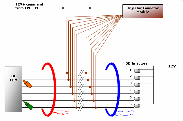
Figure 1
Ordinarily, current-clamping the live supply to a component is regarded as normal practice but here, where the LPG intervened way down in the circuit, I was in danger of perhaps missing important circuit activity. I needed to go straight to the back of the ECM – to see what it was seeing. With the hook-up in place, it was a matter of waiting for the engine to stumble again, then stopping the recording session to scroll back.

Figure 2
CHA (blue trace) is monitoring current just below the injectors and helps the analysis by giving me a point in time when the LPG becomes active. We see all subsequent injector ramps disappear as the emulator intervenes and diverts the current path. The spurious line activity seen after 1.5 seconds holds no diagnostic relevance.
CHB (red trace) clearly shows a single missing injector ramp (arrowed) indicating a problem with that injector circuit: this is the fault. Note how the circuit was performing fine until the LPG activated, and it’s this which gives us the biggest clue. The advantage of measuring current is the automatic presence of circuit resistance and circuit voltage; anything wrong with either of these factors will have a direct impact in the current reading. More analysis is needed to determine which has failed. A side observation: the overall lower-than-normal current peaks which the emulator creates yet are accepted by the OE ECM during normal driving. I had an opportunity in a subsequent drivability problem to further test injector fault tolerances, which I hope to release soon.
CHC (orange trace) simply gives me a known good injector circuit to use and as expected everything appears normal. The OEM driver delivers a good ground pulse and the emulator module is receiving a good 12 V+ circuit supply.

CHD (green trace) provides much-needed additional information. With the OE injector driver at rest (no load) I measured near-battery voltage at the ECM. This is important as it validates circuit continuity from the power source, through the emulator module, and up to the ECM. During our fault period, the injector driver is seen pulling the circuit to a good ground level, and this should now enable current to flow. What dictates the amount of current flowing is left to circuit resistance, and it follows that because we see very little current there must be a high resistance present – Ohm’s Law. After eliminating any cabling/connector issues I arrived at the emulator’s door.
There are other tell-tale signs in CHD indicating a high circuit resistance problem. First is the slight drop in open-circuit voltage after LPG became activated. It’s only small but should not be there. Second, we’ve lost the characteristic inductive kicks which are still present in the known good circuit CHC. Our high resistance is limiting current flow through a coil, dramatically weakening the magnetic field produced, and resulting in little or no energy available to induce a noticeable back EMF when the field collapses. Injector emulators have had to keep up with modern OE fault recognition so most new units cater for this inductive kick.
The emulator was an epoxy-sealed unit with no access inside to take things further, but by capturing the fault in detail and using Ohm’s Law I managed to “X-ray” the module enough to prove the fault and finally condemn the unit.
Some readers might ask Why did the misfire occur at all? considering that, at the time of the fault, the car was being fuelled by LPG and running quite happily. It’s a question I asked myself. I discovered that the misfire condition was not immediate. When the ECM had recognised a problem with No. 5 injector, it continued pulsing for a short time while evaluating the problem – is it a brief glitch or is it something more serious? When the injector current didn’t return, the ECM defaulted to emission protection and cancelled cylinder No. 5 injection and ignition, and these signals remained off-line until the next key off/on cycle. It was the eventual loss of ignition that resulted in misfire.
With this unusual problem, I can imagine that the ECM was a little confused by having an injector circuit off-line while crankshaft acceleration information showed all six cylinders firing: very odd. The ECM had the final word, though, by cancelling ignition – let’s see you fire now!
Rosen
December 07 2011
Hello Nick, I understand it all but one. Why this occur only to cylinder No.5 ? We have a problem like this but with BMW 5 E39 523i. Can you give us a clue how to resolve the problem?
Many Thanks!
Rosen
Dave Foye
March 26 2011
Hi Nick
I have read a few of yoru articles now and your presentation and explanations are top notch. I have paid for courses that aren’t as good as this !
Very good use of lateral thinking and electrical laws, very impressed.
Dave F


