PicoScope 7 Automotive
Available for Windows, Mac, and Linux, the next evolution of our diagnostic scope software is now available.
Automotive guided tests
Library of examples on how to perform tests when using PicoScope.

Training
Our collection of training videos, articles, guides and information on training courses.

Waveform library
The Waveform Library is a global database of waveforms uploaded by PicoScope users.

Case studies
Real-life case studies show how the professionals use PicoScope to diagnose vehicle faults.

A to Z of PicoScope
Detailed description of various PicoScope software and hardware features.

Videos
Training resources and demonstrations on PicoScope and the Automotive Diagnostics Kit.

Newsletter
Archive of our monthly Automotive Newsletters.

Documentation
Download manuals, brochures, posters, and training materials.

Reviews and awards
Accolades for the preferred diagnostic tool for service centers and vehicle manufacturers.

| Vehicle details: | Ferrari 360 |
| Symptom: | Intermittent non-start |
| Author: | Nick Hibberd | Hibtech Auto-Electrical Diagnostics |
The car came in with an intermittent non-start complaint, but after quizzing the customer it became more of a “no crank” problem. The vehicle was an F1 model with electro-hydraulic gear shift, where the crank command starts from the ignition switch, goes through a charge cut-out relay and through the dedicated crank relay, and then makes its way to the Transmission Control Unit. Only when the TCU recognises it’s safe to start will it then emit its own crank signal (negative switched) to the crank relay; so there’s plenty to consider.
The vehicle was tested many times with no obvious problem noted. Good battery voltage, good starter response, seemingly good cranking RPM; not much to report. The engine was tested cold and then left running for a while to see if temperature was an issue, but the customer’s complaint just wasn’t present. It got to the stage where the vehicle’s battery was beginning to suffer, so it was looking as if the car would be returned to the customer with “fault not present” written on the job card.
One remaining check was to get a capture of the starter motor operation through the eyes of a scope. A good all-round check is to look at motor current draw against solenoid exciter command (supply voltage or current draw), because it’s useful to see these factors interact. To get the most accurate record of solenoid supply voltage, it would be ideal to collect these readings close to the starter unit itself, but the unit is mounted on the underside of the drivetrain. Gaining access requires waiting for a spare ramp and then removing an entire engine bay undertray, which is time-consuming. In this game there is a constant pressure for diagnostics to be time-efficient. Signal waveforms recorded by a scope are often bursting with information, and if analysed properly, can either eliminate a component failure or prove it.
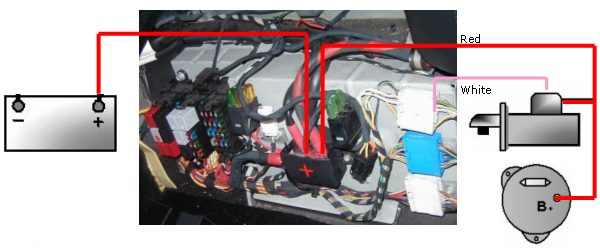
On this vehicle model, mounted behind the left-hand seat, is a battery positive distribution block where the starter supply cable joins; an area that also houses the starter exciter cable. A great second option for a starter motor test location.
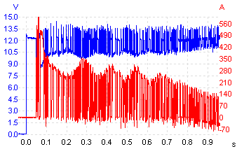
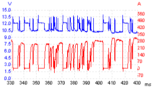
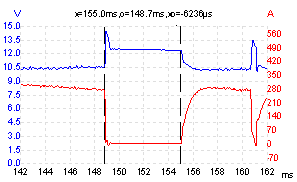
This was the result. Channel A (blue) is monitoring solenoid supply voltage and channel B (red) is monitoring motor current. There’s something very wrong with this one.
Let’s look at the same capture in more detail:
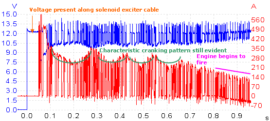
The overall structure of the capture contains abnormal signal drop-outs throughout the entire cranking event. Nevertheless, the trace still shows recognisable features of normal starter motor operation.
Capture begins with the starter solenoid receiving a 12 V exciter signal. This closes the internal contacts, simultaneously throwing a pinion drive into mesh with the flywheel and supplying battery voltage to the motor to begin cranking. Note the delay of about 50 ms between exciter feed and motor current: this is the response time of the solenoid. Any long delay here would indicate that the solenoid winding is receiving voltage but the motor isn’t reacting quickly enough; likely causes would include poor internal solenoid contacts or a possible motor ground path problem. Taking any suspicious readings here further, solenoid current draw would be analysed to see if an adequate magnetic field is being generated. This of course is just an example, as the delay time here is normal.
The cranking pattern is easy to see in the motor current waveform. On a good capture we are looking for relatively smooth and even peaks within the trace, each peak correlating with one cylinder as it approachesTDC on compression. There is a moderate current as the motor pushes a piston up its chamber, then a higher current as the piston stroke begins compression and the motor has to work even harder to compress the chamber’s fuel/air mixture.
Behind this simple explanation is a more detailed theory of how the motor draws current depending on its mechanical load. Briefly, the motor creates an electromotive force (EMF), increasing with speed, in the opposite direction to the voltage supplying it. This reverse EMF reduces the current flowing into the motor. The heavier the load on the motor, the slower it runs, so the smaller the reverse EMF and the higher the current. Each cylinder’s compression directly matches each current peak, and a noticeably low, high or uneven peak should raise questions about that cylinder’s compression efficiency. It’s also possible to identify the offending cylinder by displaying the cranking trace against any cylinder's coil signal; now just count along the number of cranking current peaks in accordance with that engine’s firing order until the suspected cylinder is named and shamed. With a good sample rate on the scope trace and a decent current probe, you’d be surprised how accurate this technique can be at spotting potential problems, but I would never consider it a replacement for mechanical compression and cylinder leakage checks.
Lastly, we see the general trend of the current signal falling at the end of the trace to a negative value. This is because, when the engine fires, a current flows from the generator towards the battery, in the opposite direction to the motor current. When the motor current intermittently drops to zero, the sum of these two currents becomes negative. Referring back to the basic schematic it can be seen that the test point where our readings have been recorded also includes generator output.
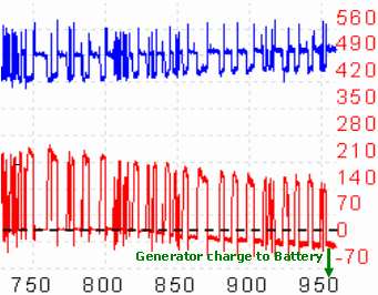
Here is the last part of the captured trace shown in more detail. Just before testing, the current probe was finely adjusted to 0 A, enabling any measured current flow to be centred on the 0 A line (just good working practice).
Ignore the voltage trace on the exciter line for a moment. As the motor rotates, current is naturally being drawn from the battery; here it’s displayed as positive current flow. Suddenly the engine begins to fire and the generator starts producing current in the opposite direction along the same cable. The probe picks this up and we see a current value starting to appear on the other side of 0 A line; this is energy being put back into the battery.
If the capture is analysed carefully, the peak-to-peak current draw from the battery is actually decreasing slightly as the motor robs current from the generator’s output that would otherwise be heading to the battery. Of course this interaction between battery, starter motor and generator during cranking occurs pretty quickly so there is no danger of the generator being burdened too much. This is one reason why the generator is designed to produce current only above normal cranking RPM.
The focus of the investigation turned to the signal drop-outs themselves. To put the captured signals in perspective, we need to remind ourselves what we are looking at in relation to the starter motor itself.
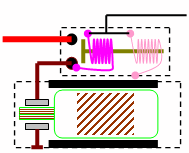
The starter motor needs to develop a high torque to make the engine fire, and to do this it needs a lot of current. This simple illustration shows the path of the starter current. Once the exciter cable has energised the solenoid, current flows from the battery, across the now-closed solenoid contacts, and leaves the solenoid through an insulated fly-lead into the motor’s yoke.
Normally with this type of assembly, two positive brushes are set 180° apart (either horizontally or vertically) to pass current directly to the motor windings; then, to complete the circuit, two negative brushes are set 180° apart in the same plane. The unit was a warranty item, so unfortunately it was not possible to dismantle it to examine the construction method.
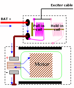
How the solenoid manages to get the heavy contacts to close, and keep them closed, is a clever arrangement. It uses two separate coils; a pull-in coil and a hold-in coil, both of which are placed around a sliding plunger in such a way that their magnetic fields push on the plunger. The sliding plunger tries to centralise itself within the magnetic field, thus closing the contacts at one end of the plunger. Electrically speaking, the solenoid has two main objectives: to engage the plunger, and to keep it engaged as long as required. It’s quite possible to do both jobs using just one coil, so why have two?
In any solenoid, the magnetic field needed to start the plunger moving is stronger than that needed to keep it engaged. If we had one coil for both jobs, the amount of current needed to generate sufficient magnetism to move the plunger would be more than is necessary to merely keep it in place. This would be a waste of energy, heat, and vital cranking amps that the battery is better spending on the motor itself. An improved solution would be to have a powerful electromagnet to get the plunger moving, and then use a smaller electromagnet once the plunger is in place (two coils of equal ampere-turns would also work).
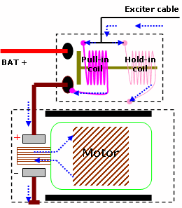
The exciter cable feeds both coils with battery voltage at the same time. To energise both circuits, the hold-in coil is grounded through the solenoid casing whilst the pull-in coil receives a ground path through the motor’s windings. The combined force of both coils moves the plunger in place; as the solenoid contacts close, our pull-in coil has done its job and can now be disconnected. It can be seen that once the contacts close, battery voltage is supplied not only to the motor but also now to the ground side of the pull-in coil. Since the pull-in coil is already being supplied with battery voltage from the starter relay, the potential difference across the coil drops to almost 0 V, which cancels any current flow and subsequently any electromagnetism the coil once had.
The hold-in coil’s operation on the other hand is much simpler. Having a permanent connection to ground, from the moment a crank command is given, the coil remains fully energised until the crank command is released. This way the coil is always ready to hold the plunger whenever the pull-in coil is disconnected. That’s how it works.
From our test point where the measurements were taken, and the cranking current trace, we can safely say that current flowing into the starter assembly was intermittent, and for the moment that is all that can be deduced. So we now have to build a case using this sole fact arguing for and against possible causes.
A current reading of any kind in a circuit without voltage present is impossible. From this we can deduce quite a bit. Voltage would have to be in good supply to keep the current level of the motor at 250 A plus. Also remember that the engine’s RPM during cranking seemed fine. It could be perhaps this main cable was making and breaking a contact, thus causing our current signal drop-outs, but this explanation didn’t seem to fit
A check of the voltage level at the power distribution block showed a good battery voltage present before, during and after the current signal lapses. This eliminated everything before the distribution block towards the battery. Admittedly, because our test location was in the middle of the power supply line, this did leave the power cable travelling from the distribution block to the starter motor. A cable connection problem onto the solenoid wasn’t considered likely because of the sheer nature of the current lapses. The drop-outs were quite sudden and cleanly defined, and this together with the lapses appearing very quickly didn’t make a strong case for the theory. A decisive factor against a power cable connection problem came later.
Neither was there any obvious sign of connection resistance. The scope never shows an insufficient current level, only small current peaks that haven’t had a chance to reach a normal operating level before being cancelled again. This signature is very different from a high resistance causing low current flow.
A low battery supply was immediately ruled out because this would affect the circuit’s overall current flow; not as in this case where our fault allows current flow to disappear, and then reappear.
This is very similar to the above case. A current can flow only from a high potential to a low potential. Both potentials would have to be present to see the recorded normal current level in between the lapses. It’s not a normal characteristic for a poor cable connection in either supply or ground path to cause a repetitive signature. In this instance, a load of 250 A plus on any circuit would itself find a connection problem and usually bring the circuit down permanently.
Not mentioned yet is that this vehicle model has a battery isolator installed between the battery’s negative post and the chassis. This is definitely a likely cause if the ground path was ever suspected as a problem. But the trace shows something that could completely rule this out. The exciter line potential was taken with channel A referenced to a nearby bolt screwed directly into the chassis framework. If this channel is still measuring a good potential difference then the scope’s ground connection, and therefore the isolator, must be good during our fault.
This one couldn’t be ruled out as it’s the solenoid that delivers current to the motor, and if this isn’t done efficiently then problems will arise. One possible explanation for the current level drops is if the solenoid releases control over its plunger, thus opening the contacts. This might include the crank command being poor or indicate a problem with the hold-in coil, but we need to consider something. If the hold-in coil was failing causing the plunger to retract, this would in turn throw the pinion drive out of mesh with the flywheel; a noticeable “clunk” would be heard. As our fault is quite repetitive, the “clunk” would turn into a nasty “chatter”. Neither condition was evident at any point in the investigation. Clues were all pointing to the drive gear being held in place during the fault and it was backed up with a healthy voltage level present along the exciter line before, during, and after the fault.
We know the voltage was healthy because if the exciter circuit was going open and maybe even causing the fault, we would expect to see a higher voltage level than that shown; but we do not, indicating that an electrical load is still present on the exciter line during the fault. Any doubts here would have been further investigated with a low-level current probe.
A problem with the pull-in coil itself could be eliminated, simply because the starter motor always responded to the crank command given.
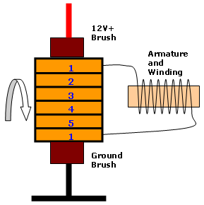
Commutation is the point where the motor brushes glide across the many commutator segments as it rotates. The commutator bars come in pairs, each pair connected to one insulated winding which is wound onto the armature. This basic illustration shows segments 1 connected to a power source. This creates a magnetic field in No.1 winding which works against the field poles (not illustrated); and this consequently rotates the armature which brings in the next segment pair and the process starts again. A typical armature houses about 30 segments, feeding 15 armature windings. These pairs are usually orientated on the shaft to match the polarity of the brush fixings (actually it’s more correct to say the polarity of the brushes match the armature windings).
A commutation problem isn’t ruled out. For instance, a broken brush spring will cause insufficient contact pressure on the commutator, thus developing a possible loss of brush contact. No brush contact means we will lose current supply. As a general rule, most starter units house two positive brushes and two ground brushes, so the fault would have to affect both brushes on either potential.
An open circuit in one of the windings would cause a current signal dropout, but it would also leave a very distinct pattern in the captured current trace, certainly more regular than ours. A short between windings was ruled out, as this would show dramatic positive current peaks, and again this would be very regular.
Even though the capture isn’t yet telling what the fault is, it is starting to tell what it’s not. There was something else in the capture that needed explaining before arriving at any conclusion.
The voltage level along the exciter line is seen to drop whenever motor current demand is high. This comes as no surprise; the motor draws 250 A and will inevitably bring down battery voltage slightly. Our crank command comes indirectly from the same power source, so it makes sense that this will be affected to a similar degree; in this case down to a healthy 10.5 V. What is interesting are the peaks seen on the exciter line immediately after the motor releases electrical load (during our fault). The hashed line in the exciter line shows the voltage level present during a motor current lapse and can be taken as near battery voltage; it’s marked as being around 12.45 V. The hashed line in the current trace represents 0 A.
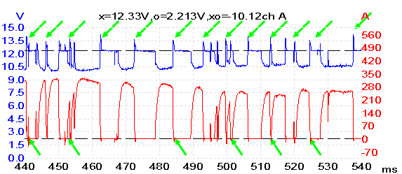
Both measurements show activity past their normal working values for a crank condition. We see the exciter line exhibit brief voltage peaks higher than battery voltage the exact moment we lose current draw; these are most definitely linked. Also, the current trace shows similar characteristics where current is no longer flowing from battery to engine bay components (generator and starter), very briefly flowing from the engine bay towards the battery.
We know what these peaks represent, but how are they linked to the fault?
Out of all the theories put forward only one stood from the rest which includes the fault and these “peaks”.
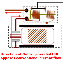
At the beginning of the investigation it was stated that the motor behaves like a generator that opposes the current flow supplying the motor, and as motor rotational speed picks up so does the EMF generated. It seems that it’s this EMF that is contributing to the “peaks” during the fault.
First of all remember this EMF is between chassis ground and battery positive, and it’s the same voltage reference that the scope is measuring on the exciter line.
Secondly, we know that the probe is seeing no current flow during the fault, which ultimately means a break somewhere in the motor circuit, and if there’s a circuit break within the motor yoke, any EMF generated is no longer referenced to chassis ground so the scope will struggle to pick this up. The fact that the scope is picking this up means the open circuit isn’t within the motor structure. We can go further and say that because the current probe isn’t registering the same degree of EMF burst below the 0 A line (current returning to battery), very little of the generated EMF is coming through the main supply line. The peaks seen on the exciter line were coming from somewhere else.
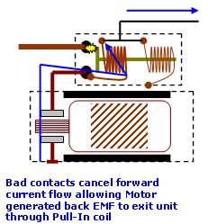
Applying these facts to the illustration can lead to only one realistic explanation — the solenoid contacts.
If the contacts are bad (making and breaking) this will immediately drop the overall main line current flow. Because the motor is intact, it continues to generate (for a very short time) reverse EMF proportional to speed. The EMF is allowed to escape through the pull-in coil and enter the vehicle’s electrical system.
All of what has been discussed sounds very dramatic, to the point where it’s hard to conceive that initially during testing no noticeable fault seemed to be present. But in reality the fault never lasted much more than 6 ms (0.006 s), and although it would be difficult to put into figures, the percentage of time spent with current flowing far outweighed the time spent with no current. So when you put this in perspective with the problem, without a scope this fault would have been near impossible to spot.
This case study might seem too involved for a humble starter motor complaint, but from the time it took to capture the first trace to eventually condemning the unit, the problem took little over 10 minutes and all done with only one scope hook-up location. What has taken up much of this study’s time is the need to explain the wealth of information hidden within the recorded waveforms.
The following waveforms were taken with a new starter motor installed.
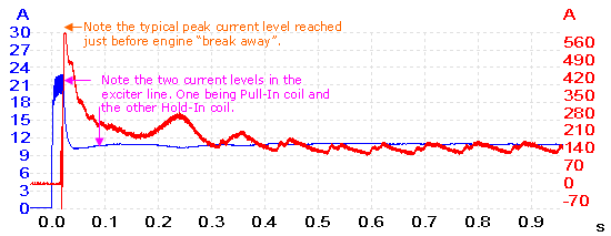
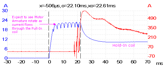
Channel A measures starter solenoid current, and channel B is starter motor current.
Robert Lesaca
April 16 2015
I have worked on starters before, repairing them mostly and quite familiar with its mechanical workings. And with the new PICO I got last year, I am excited to read in-depth analysis of waveforms which I am trying hard to absorb and understand (I am “weak” when it comes to the electrical aspect). But this is a new challenge for me. Thank you so much.
sigoaprendiendo
March 07 2015
It is a very interesting case. BTW is it possible to get the psdata file to study it better. Particularly I would like to zoom in the first 200 ms and see if the reverse EMF is seen on the exciter
Kind regards
sigoaprendiendo from picoauto forum
Dario Caraballo
March 07 2015
Hi
I wonder why there is no voltage measurements for exciter circuit on the new starter motor installed, so that the comparison game would be completed and more interesting as well
Kind regards
sigoaprendiendo from picoauto forum
M. DeAbreu
March 30 2013
Very in-depth but I would suggest that the last figure actually shows contact bounce on the solenoid exciter line and not the armature spinning up as the current sense is completely flat for the majority of the initial contact closure and the repetition on the excitation line is extremely symmetrical. You do finally see the current line begin to show the armature move towards the end of the excitation pulse. This is due to the field finally beginning to form.
I also wonder why they would use a more expensive Two-coil exciter system when simply stepping or modulating the single coil with a mosfet would probably be cheaper and make for a simpler starter as well as remove the need for an actual mechanical relay.
Just my thoughts.
Brucestafo
May 13 2012
This article shows that to be able to extract as much information from a scope trace, a technician should have a very good understanding of the theory behind the system being tested. This is a very good analysis. Thanks.
troubleshooter
November 14 2011
thanks so much for your comprehensive sharing of intelligence. this is one i’ll archive and keep for a while!
Rimvydas Gerasimas
July 28 2011
Perfect tutorial . Great ability to explain things clear and simple . Thanks.
Errol Ince
March 11 2010
Excellent diagnostic explanations, system〈s〉 operation and great colourful and clear illustrations. Made me buy a Pico scope and I’ve got most of the other high quality motor vehicle alternative OBDII code readers, including one with an integral 4 scope meter, but its not even close! When the OBDII code is not right or clear, I think you need a Pico and its tutorial package! But please more on actual CAN BUS real-life faults, diagnostics and what the faults was? p.s. The Frank Massey free and supplied CDs with the scope are also great, particularly for me; as I teach motor vehicle in a college and through the tutorials I have developed and updated my and my students’ skills.
John Cartmell
March 10 2010
Thank you for making this very interesting article available online.
Joseph Tucci Jr.
January 23 2010
Avery good job of finding a verry tough proublem! I have not used a scope since 1973 this web site has really opened my eyes to the new line of scopes and thare need I gotta get one!!!!!!


