PicoScope 7 Automotive
Available for Windows, Mac, and Linux, the next evolution of our diagnostic scope software is now available.
Automotive guided tests
Library of examples on how to perform tests when using PicoScope.

Training
Our collection of training videos, articles, guides and information on training courses.

Waveform library
The Waveform Library is a global database of waveforms uploaded by PicoScope users.

Case studies
Real-life case studies show how the professionals use PicoScope to diagnose vehicle faults.

A to Z of PicoScope
Detailed description of various PicoScope software and hardware features.

Videos
Training resources and demonstrations on PicoScope and the Automotive Diagnostics Kit.

Newsletter
Archive of our monthly Automotive Newsletters.

Documentation
Download manuals, brochures, posters, and training materials.

Reviews and awards
Accolades for the preferred diagnostic tool for service centers and vehicle manufacturers.

| Vehicle details: | Ford US Windstar |
| Year: | 1996 |
| Symptom: | P0174, P1537 |
| Author: | Rich Barton | C.R.B. Repair, Moville, Iowa, USA |
Technician and workshop owner Rich Barton of Iowa, USA, was shown a 1996 Ford Windstar minivan that ran well when cold, but misfired badly when warmed–up. Using scan tools gave mixed results, but a toolkit consisting of Pico Technology’s PicoDiagnostics software, PicoScope oscilloscope and FirstLook sensor helped him to pinpoint the fault. The graphical results from these tools gave him the evidence he needed to back up his diagnosis. We investigate how Rich tackled the problem with the help of technician Carl Grotti from Missouri.
Rich gave the vehicle a test drive, and it ran well with no MIL light showing. When he pulled it in to the shop, however, the engine was shaking badly, although the MIL light remained off.
First off, Rich used a scan tool to look for live and pending trouble codes, but the vehicle’s OBD II system reported nothing wrong:


Figure 2: Pending codes
These scan results show nothing except that the last technicians to work on the van had been tidy and cleared the trouble codes.

Figure 3: Fault codes from the Ford IDS
The Ford IDS managed to dig up some fault codes that the previous tools had missed (see Figure 3). These codes showed no misfires, but did flag up a P0174 (Bank 2 Lean) code, as well as a pending P1537 (IMRC Stuck Open) code.
Rich used the Ford IDS to read the Mode 6 OBD II data, but the results were inconclusive and did not get him any closer to the cause of the problem. This job was going to need some more powerful tools.
What is Mode 6 data?
When you choose a test on a scan tool, the tool sends a ‘Mode’ command to the vehicle’s OBD II system. This command requests a particular set of data from the vehicle. For example, Mode 3 is a request for the list of fault codes. Mode 6 is less well known, and requests ‘test results for continuously and non-continuously monitored systems’. This makes it useful for spotting minor problems, such as slight misfires, that haven’t triggered a fault code yet. Source: “Driveability corner” by Mark Warren, MOTOR magazine, Jun 2002
Next out of the toolbox came the new PicoDiagnostics software from Pico Technology. This program produces a range of diagnostic information by interpreting tiny ripples in the battery voltage, and works on any make of engine. It is quick to use, as it needs only two crocodile clip connections to the battery. It’s also free of charge to all owners of Pico Oscilloscope Diagnostics Kits.
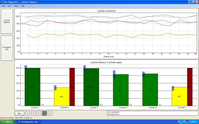
Figure 4: PicoDiagnostics cylinder balance test. There’s an obvious misfire on two cylinders.
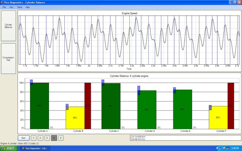
Figure 5: The same PicoDiagnostics test showing engine speed variation.
For comparison, here’s what the Ford IDS made of the same engine:
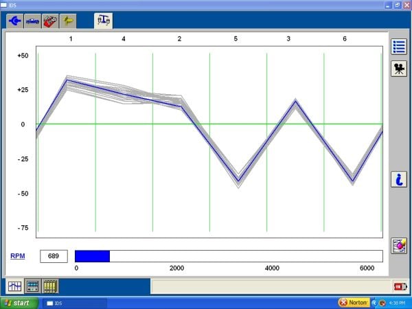
Figure 6: The Ford IDS power balance test told a similar story.
Next, Rich ran compression tests using the two tools, and both sets of results agreed, proving that there were no leaks. This ruled out a head gasket problem, which might have been expected on this engine:
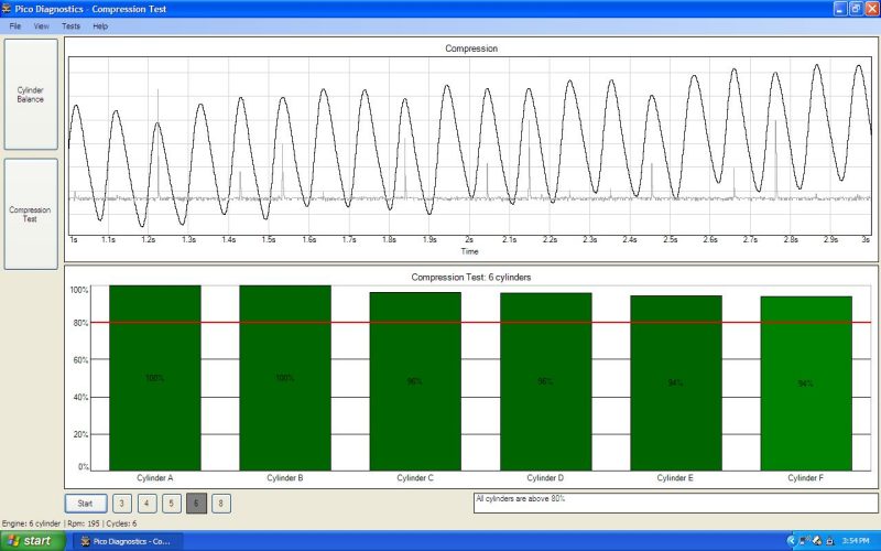
Figure 7: PicoDiagnostics compression test results

Figure 8: Ford IDS compression test results
With the engine warmed up, Rich grabbed some real–time scan data. The abnormally high fuel trim values (SFTRIM and LFTRIM) on Bank 2 seemed to point to an injector problem:

Figure 9: Scan data from the warmed–up engine
On the next scan, the O2 sensor signal on Bank 2 showed a lot of hash, which might have indicated a fault. The sensor looked as if it had been disturbed recently, so Rich removed and inspected it, but found it in perfect condition. Both O2 sensors responded normally to an injection of propane, so there was evidently nothing wrong with them.

Figure 10: O2 sensors during a cold start, showing a lot of hash on Bank 2
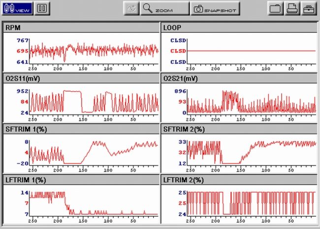
Figure 11: Scan data, showing the response when propane was added
As a precaution, Rich also checked the plug wire routing and connections on the suspect cylinders, but these were fine. He even checked the intake for leaks, as this is a common problem with these vans, but found nothing wrong.
Next, Rich checked the injector voltages and currents on the two suspect cylinders, 5 and 6, using the PicoScope kit in quad–trace mode. To get maximum information, he used the two spare channels to record fuel regulator pressure as picked up by the FirstLook sensor, and secondary ignition voltage.
Carl Grotti commented that the injector voltage trace lacked the inductive spike that you would expect at the end of the injector voltage pulse, and did not show the gradual increase in voltage during the open time that would normally result from the current building up in the injector coil. The injector current traces did not have the usual hump at the point where the valve pintle should open; and the injector current was too low, reaching a peak of only 500 milliamps, compared to a normal peak of about 900 milliamps. These problems suggested a weak power supply to the injectors.

Figure 12: Cylinder 6 injector and waste spark
Rich did another couple of captures with PicoScope on longer time bases so that he could see both waste and power sparks. The #6 secondary trace (green) shows two multi–strike sparks. The spark on the left is the power spark, and the spark on the right, one complete revolution of the crankshaft later, is the waste spark. As expected, the power spark has a higher firing voltage than the waste spark, because it happens when the cylinder is under full compression. However, the persistent high voltage or “high nose” after the second strike of the power spark suggested to Carl a lack of fuel.

Figure 13: Cylinder 6 on power stroke and then waste stroke

Figure 14: Same cylinder over three crankshaft revolutions
Here is another trace showing the injector currents over a complete revolution. The FirstLook sensor trace removes any doubt that the injectors are not firing, as it shows a weak fuel pressure pulse on cylinder 4 and no pulse at all on cylinders 5 and 6.

Figure 15: All six injectors. Injector 4 opens later than the others.
The vehicle was given a complete change of injectors, a new fuel filter, and a new connector for injector 4, and the misfire was cured.
Our thanks to these contributors to the iATN Tool & Equipment forum:
Phil J
June 23 2012
on the picodiagnostics software program which shows cylinder and compressions imbalances, am i right in thinking further testing is required to establish the number of the offending underperformer as it cant identify the individual cylinders, only the fact that one or more is down on power?
Larry Dean
April 05 2012
There’s that fun case study style of Rich that i came to like on autonerdz. Sure do miss Carl, though. Anybody wants to spend hours with Rich and Carl can find numerous threads of theirs right in the archives of the autonerdz general technical discussions right here: http://www.autonerdz.com
Stuart Gover
April 02 2012
A good detailed article. Its nice to see the firstlook sensor being used with trace checking.
Its also a valuable learning point looking at both Voltage AND Current together to get the full operational picture of the acutator (Work request vs. work done)
Well done.
Tom Roberts
March 29 2012
Both Rich and Carl learned PicoScope as members of the Autonerdz Picogroup and have been valued contributors to The Autonerdz Community Forums for many years.
Carl passed away last year but we can all still learn from his many threads in the forums archives. Carl was our first PicoScope customer and later became our Midwest USA affiliate. We sure miss him. He had a very unique and intuitive diagnostic process and left us hundreds of case studies as his legacy.


