PicoScope 7 Automotive
Available for Windows, Mac, and Linux, the next evolution of our diagnostic scope software is now available.
Automotive guided tests
Library of examples on how to perform tests when using PicoScope.

Training
Our collection of training videos, articles, guides and information on training courses.

Waveform library
The Waveform Library is a global database of waveforms uploaded by PicoScope users.

Case studies
Real-life case studies show how the professionals use PicoScope to diagnose vehicle faults.

A to Z of PicoScope
Detailed description of various PicoScope software and hardware features.

Videos
Training resources and demonstrations on PicoScope and the Automotive Diagnostics Kit.

Newsletter
Archive of our monthly Automotive Newsletters.

Documentation
Download manuals, brochures, posters, and training materials.

Reviews and awards
Accolades for the preferred diagnostic tool for service centers and vehicle manufacturers.

| Vehicle details: | Unspecified |
| Symptom: | ABS fault |
| Author: | Nick Hibberd | Hibtech Auto-Electrical Diagnostics |
The vehicle came in with the complaint that the ABS could be felt working through the brake pedal at very low speeds. I carried out a short road test to verify the complaint and, sure enough, the ABS would cut in at very low speeds; in fact, just before the car came to a stop. Apart from this the car, including the ABS system, worked as normal. Obviously the car didn’t need any ABS intervention, so let us approach this problem with the question, “What is the ABS seeing where it feels it needs to intervene?”
Thinking back to the basics of ABS strategy: it monitors all four wheel speeds and, when the brake is applied, it looks to see if any wheels decrease in rotational speed at a higher rate than the others; this would indicate that a wheel is about to lock up. The modern equivalent is now called Stability Control and is far more advanced than just ABS. This vehicle is also equipped with Anti-Skid Reduction which basically works in the opposite way to ABS; if there is any increase in individual wheel speed relative to the others (wheel slip during acceleration), then the affected wheel will receive brake pressure to reduce the slip. During this wheel slip phase, it is normal for the engine ECU to offer torque reduction, which can come from killing the injectors, ignition retardation or other means. However, with all this advancement, we come back to the fundamentals where individual wheel speeds are closely monitored. We can conclude that we are dealing with the ABS strategy rather than ASR because, quite simply, the brake pedal is being applied during the fault; this eliminates ASR and gives one less aspect to worry about.
It was noted that the ABS MIL didn’t flag before, during, or after the ABS intervened, but the MIL did correctly illuminate at key-on as normal. This is a clue that the ECU seems happy enough with its operation and that the system appears only to be acting upon information supplied to it; it sees itself as merely doing its job.
Now it’s time to hook up the scope.

The above capture was taken at about 10 mph, with the brake pedal released and with no ABS intervention. Channel A (Blue) is monitoring RH rear WSS (wheel speed sensor) and channel B (Red) monitoring LH rear WSS.
Note: Both of these readings were recorded with the scope referenced to chassis ground — it’s important to be aware of the test conditions when looking at a suspect signal. From this capture we can see there is a clear problem with the LH rear WSS.
To interpret the trace correctly and form a conclusion from it, we need to understand what we are looking at.
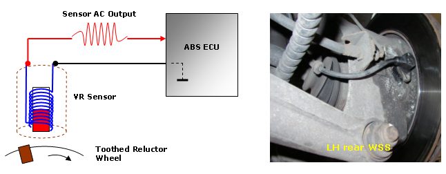
The system uses four variable-reluctance sensors, one attached to each corner hub. Touching very briefly on sensor theory; the output of this sensor is alternating current which is generated as a moving reluctor (a metal object, in this case our wheel rotor) passes into, through, and out of the sensor’s magnetic field. The signal signature is determined by only a few key factors that need to be highlighted:
Each factor plays a very important part in creating a valid signal; lose any one of these and the output signal will suffer! As the reluctor moves into the sensor field, a positive EMF is generated, and as the reluctor moves away from the sensor field, a negative EMF is generated, usually with the same amplitude as the positive peak. We can say that each positive peak represents one reluctor or tooth on our rotor wheel (not a strictly true analysis, but it’s good enough). I’ll leave the theory at that, as I’m sure the reader is well aware of this sensor and its operation. This of course is how to create a signal, but what any individual application does with this signal is an entirely different matter. This particular system has one of the sensor cables grounded through the ECU, leaving the other cable as the main speed output signal back to the ECU. If we look at capture 1 closely we will see both outputs centred just above 0V, but don’t confuse this with a “floating ground” signal reading.

As mentioned, the ECU applies a ground to one of the sensor outputs, so ordinarily we would now expect to see the generated AC centred around this potential. However, this system also fixes the sensor output line at 0.18 V (as a diagnostic aid for the ECU), so now the sensor generated AC rides along this new reference. See capture 2. All of the sensors on this system matched this signal characteristic

Referring back to capture 1, this small extract shows a poor signal being generated; so something is wrong with one of the key factors mentioned earlier. From the mere fact that the sensor is able to generate a suitable output for the given wheel speed, we can rule out sensor magnet strength, number of windings, and speed of reluctor. These are pretty constant factors here and it would be ridiculous to think that any one of these was absent at that one particular time. To anyone who hasn’t seen this kind of abnormal signature before, it’s very indicative of a failed reluctor wheel. We are left with shape and composition of reluctor and distance between reluctor and sensor.
A closer inspection of this reluctor was needed.

With the LH rear driveshaft removed, a possible issue was found with the rotor. Notice the unusual shiny spots on some of the teeth. Was this the problem?
This doesn’t seem to be an issue. The affected teeth still had good structure compared to all the rest. This means good height, tooth width, good general dimension, and good spacing between the teeth. According to the capture, our problem is only in one area of the rotor, and these shiny spots correlated well with the recorded capture, but a distance problem between sensor and tooth isn’t the problem here.
The shape of the teeth has already been covered and eliminated; it was the make-up of the shiny spots that was now in question. The sensor houses a magnet and relies on the reluctor being easily susceptible to a magnetic field. If the material used as a reluctor is made from a weakly magnetic (non-ferromagnetic) material, the sensor’s own magnetic flux will not change easily; and no change in flux means no signal generated.
A dead simple way to test the magnetic properties of the reluctor (our teeth) is to hold a known good magnet close to the teeth and feel the force of attraction. It’s not very scientific and seems a little crude, but it works, and judging from the scope capture we should experience a distinct difference. Several teeth outside the suspected area on the rotor were checked like this to gain a sense of what force to expect. When the shiny spots were checked, a low magnetic attraction was felt. The capture shows the shiniest teeth generating the lowest EMF, as indicated 1 and 2.
It was later discovered that the vehicle owner had had some extensive work done previously in that corner of the car, and this rotor had subsequently suffered damage and been repaired. The repair was actually very good work from a machining point of view but, unintentionally, the repair didn’t agree with the WSS. How is this linked to the ABS activating when approaching a stop?
First of all, remember that this capture was taken at 10 mph, which is well above our braking to a stop speed. In hindsight, a good signal relationship would have been to view LH rear WSS against ABS pump command; this way we would have seen what signal threshold the ABS decided was enough.

The amplitude of the signal from our LH rear WSS had clearly been affected by the rotor repair, but the frequency of the signal still remained. And if the frequency still exists, we still have a valid wheel speed signal, in a way. Eventually, as a result of our poor reluctor, the wheel speed will drop to a level where the poor reluctor teeth can no longer generate a valid speed signal.

We are left with a situation where, during braking and at very slow vehicle speeds, the ABS will wrongly interpret this weak signal as wheel lock-up and so activate the ABS: our vehicle complaint!
A new reluctor wheel was installed. Did this cure the problem? Read on to find out...
The fact that there is a part two to this article should have suggested that cleaning up the LH rear wheel speed signal didn’t solve the problem. During the first few yards of driving after the repair, the ABS kicked in again when approaching a stop. There was another problem somewhere.
I sat in the car and thought about the fault found and the repair. Everything pointed to a wheel speed sensor (WSS) problem, and one had been found, so it was back to the beginning.

Not mentioned in Part 1 was how and where the signals were picked up. I like to go directly to the ECU pins so that I see through the scope exactly what the ECU sees. For different reasons in this particular instance, I elected to go straight to the WSS themselves. It proved a little awkward because there was no chance of back probing the pins on the WSS connectors, but I found a way: I looped cable strands around the speed signal male pin that were just thin enough to enable it to fit back together without damage.
Capture 1 was taken at about 10 mph. This is another good reason to correlate WSS signals on the same axle, as the frequencies of the signals should be near identical. Look carefully for differences between the signals. It is common for a system to have a different number of rotor teeth on the front and rear axles, but there is never a difference between the LH and RH sides. I’ve even witnessed tyres of the same size but from different tyre manufacturers on the same axle resulting in different wheel speeds! I always recommend to the vehicle owner to fit the same manufacturer’s tyres — preferably all round, but definitely on the same axle.

Here the signals and frequencies matched. If we really scrutinise the capture we can see a slight peak-to-peak difference between the two, but this shouldn’t matter too much as there is always a slight discrepancy between sensors. So now what? I wasn’t about to give in on the possibility of a WSS signal problem causing this vehicle fault, and at my last count cars had four wheels. I decided to check the front axle WSSs. In this case, I knew that the frequencies could differ between the two axles, so I was more interested in the signal amplitudes.


Captures 2 and 3 were taken at about 10 mph, and this time they show the WSSs on the same side. Immediately there’s a problem: the front signals have badly lost amplitude. Don’t pay too much attention to the sudden bursts in EMF in capture 2, as this was due to interference entering my make-shift test cables scattered round the car.
Something struck me as odd: both front signal amplitudes were reduced by the same amount. One reduced sensor signal would definitely indicate a fault, but with both WSSs on the same axle showing almost identical signal shapes, I briefly considered this as being normal! At this point I began to doubt my measurements. I took several captures of these signals, making sure the connections were good, the correct sensor cable was being monitored (remembering that one of the cables is indirectly connected to ground), the scope grid was set up correctly, swapping the channels over in case I had a leak to ground, and anything that could possibly explain both sensors reading the same low amplitude.
I eventually concluded that this couldn’t be normal for the exact same reason I condemned the LH rear sensor signal in Part 1. In this case, when approaching a stop, the front sensor signals became become too weak for the ECU to correctly register the vehicle speed; and because the rear sensors were still producing a good signal, the ECU would have assumed that the front wheels had locked up and so activate the ABS.
Normal or not, the findings do relate to the initial game plan of a sensor signal problem.

Here the WSS and associated cabling total a resistance of 1.734 kΩ
I set out to find a common factor linking both WSSs which would cause the low-amplitude signal. I extensively investigated both front WSS circuits for possible leakage to battery negative, battery positive, each other, all other cables within the ECU block, ignition on and off, high resistance within sensor cabling, ECU connected and disconnected, and everything else I could think of.
In short, I was struggling to find anything electrically wrong, and there was certainly nothing to suggest that these sensor circuits had something in common, other than the normal sensor grounding path through the ECU. This also checked out OK.
So if not electrically, what about mechanically?
To investigate a mechanical reason for the poor signal amplitudes, we now need to focus on the wheel hub at each corner of the car, which means we are no longer looking for a common link but more of a coincidence that just happens to affect both sensors to an equal degree. As an Electrical Tech I’ve been caught out more than once when dealing with coincidences, but in this case I didn’t have much else to go on. I approached each problem WSS individually and for the moment ignored the fact that two WSSs had been affected. What was I looking for?
Nothing has changed from the operating factors explained in Part 1. In order to create a valid wheel speed signal from a variable reluctance sensor, we need only a few key factors:
We can’t rule this one out. If the magnet held within the sensor’s core has deteriorated or degraded, the passing inductor (toothed rotor) won’t distort the magnet’s flux to the same degree and so we end with a weak generated EMF — the fault. I’ve had past instances where the sensor magnet has been reduced to almost powder form.
This is very unlikely. The number of windings makes up nearly all of the sensor’s resistance and this has already been verified at 1.734 kΩ. It is, however, possible for the windings to short together internally, but this would result in a reading lower than 1.734 kΩ depending on where the short was inside the sensor windings. The fact that we have a good sensor resistance reading means it’s safe for the moment to exclude this.
This again is very unlikely. Firstly, if the composition of the reluctor were affected, each tooth would have to change by the same amount, which seems highly improbable. Secondly, if the shape of the teeth was wrong, every one would have had to be affected in exactly the same way. The captured signal showed no missing or bad teeth, only a low amplitude.
This is the favourite, based on my experience and for practical reasons. A distance error between the sensor and the reluctor would leave the sensor resistance alone and the general shape of the signal intact. It’s not unusual for corrosion to build up between the base of the sensor and its face-to-face contact with its mounting, even though the two contact faces are held together with a securing bolt. The sensor rotor gap need only be altered a fraction to make a very noticeable difference.
This has to be the least likely of all. If the rotor speed was an issue, it would rightly affect the amplitude of the signal, but the frequency would suffer too. If you look closely at either capture 2 or 3 you will see that the frequency of our weak signal is almost identical to the known good rear traces, so we can conclude that the rotor is in fact rotating at the same speed.
When we break the sensor’s operation down and eliminate some of the factors involved, we’re closing in on what is the problem. It’s looking like a sensor-rotor gap problem. As long as I stick to the sensor’s basic operating rules then it should be easy.
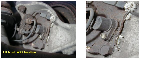
This shows the typical location of a front WSS. It mounts onto a cover plate and this plate is bolted to the rear of the hub. Firstly we can see a white fuzzy build-up around the back plate fixing bolts, and this corrosion seems to have settled in a gap between the plate and the hub face. Was it normal? Was the gap deliberate?
A quick visual inspection around the hub didn’t show much else wrong. Ordinarily I would remove the sensor and start collecting measurements to get an idea of the gap between sensor tip and rotor teeth, but with this sensor’s mounting plate being easy to remove I could now see what exactly was going on behind the sensor.
With the back plate removed, the root problem became clear.

Anon
May 07 2022
Excellent diagnosis! Even better write up!
Kuroto
January 25 2022
Thanks for going so in-depth so the rest of us can learn something. I’m getting tired of looking for knowledge and only seeing people replace parts without ever touching on the elven magic that electronics apparently are. As another bright minded individual noticed, it may not make economical sense to spend such a long time diagnosing just for the sake of getting a customer’s car out of your shop, but as someone who likes to know how shit works, I appreciate your “borderline ocd” approach.
David Lawhun
September 08 2021
Wow. I bet none of you who like this fellas analysis ever fixed one ABS fault. Just like the author never did either. Do you want to actually fix the car or dissect every slight anomaly you can find? Is this guy working at Mr Spocks Garage? No! The author isnt working on cars at all because even Mr Spock needs to find results fast. This guy has to be unemployable OCD. Did any of you think of replacing the old ABS sensors with new and be done in minutes as a maintenance. Who cares why they crapped out? Fix it and move on. I would fire your OCD asses twice!
Dave
September 08 2021
This guy is a techno book worm who over analyzes everything into infinity and never finds the answers. He is even proud when he gets it wrong. Not only does he waste his own time but now he is wasting all of our time too. Real World Pal!... Over here!!!
Joatt
December 04 2020
An excellent and instructive description for diagnosing one of the many ABS gremlins.
Alex
July 26 2020
So many explanations and at the final stage nothing about the real problem .... ughhhh
Peter Nash
September 16 2017
Can I have your email Nick I have a wss reluctor question ?
Saleem Vanker
December 15 2016
I had the very same problem twice, first on a GWM Florid and then on a Toyota Corolla. In both instances we found the car had tyres of different sizes on the same axle. The GWM had one 14inch tyre and three 15inch tyres. The Corolla had a difference on the tyre profile.
Thanks
Saleem Vanker
hari krishna
May 26 2016
This is the right way of thinking to reduce the cost on fixing cars. I really appreciate the way you have written this article.
Anonymous
January 01 2015
Truly well written. Stuctured, ratinal, knowledgeble
NICK
November 15 2012
VERY INFORMATIVE STUFF IS THERE ANY CHANCE OF RUNNING A ARTICLE ON THE NEW ABS/TRACTION CONTROL SYSTEM WITH ACTIVE WHEEL SPEED SENSORS AND HOW THEY ARE LINKED INTO THE CAN/BUS SYSTEM AS I SEEM TO BE HAVING TROUBLE GETTING SOME DIAGNOSTIC INFORMATION ON THESES SYSTEMS , AGAIN MANY THANKS FOR THIS GREAT ARTICLE
Brian Butler
November 04 2012
A very interesting article and I was glad to see some sound information before embarking on an ABS fault on my wife’s Smart car. The ABS and Trust lights were coming on at speeds above 45 MPH. Not having a portable scope I used an AC Voltmeter, to carry out a moving test, which revealed 3v & 2v RMS from the front wheels and 4v & 4.5v RMS from the rear at 30MPH. I was a bit concerned about the lowest level of 2v but after seeing the comment in your article about level variation I disregarded it. However what I did see on the voltmeter was a pulsing of the meter needle in sympathy with road speed on the rear wheels. This instigated a closer examination of the rear reluctor rings which both had a small crack due to being forced open by rust. They were both changed and the fault cleared, but it was interesting to see the waveform distortion caused by the crack when a simulation was made up on the bench using a home made sensor and fitting one of the damaged rings to a DC motor and suitable mechanism, the crack caused a pronounced amplitude blip and an unequal period sufficient to upset the ABS electronics. .(JavaScript must be enabled to view this email address)
Mirko
October 29 2012
Nice work, well done. I’ve never seen such dedication in making perfect examples. Very obvious and accurate!
Ralph Thibodeau
July 30 2012
nicely done. Explaining to customers with graphs also helps them to understand why things go bad and how we as techs get to the root cause. If cause is not fixed then we still have a comeback.
mmc
February 12 2012
Well done, indeed. I would like to thank you explicitly because I was having problem with this and could not figure out why are we getting such strange values on live data , from one WSS. Till I found this page. Thank you very much.
james thornton
April 06 2011
I may be asking a thick question. So it was the corrrosion. What Was the sensor final fix. how could you reshim and stop the corrosion so the problem would go away?
Garry Reid
June 25 2010
Monitoring Hysteresis is an excellent choice in ABS sensor diagnostics.
Well-done Nick, good description.
Gazau
Lea Pen
May 09 2010
Joseph, are you for real?
Joseph Tucci Jr.
January 23 2010
I do not se how you needed a scope to find this prob. a simple vis. insp. would have shown this.
John Mazarakis
December 01 2009
Excellent description and operation…And most important well explained….Well done!!
Ed H
August 29 2009
Hi. Very interesting. I don’t have a PICO scope but some very cheap hand held device. Big problem with ABS misbehaving and indicating that the most likely cause was reluctor ring cracked (common on Rover 400 and 45). Had both CV joints, with reluctor rings attached, replaced? Problem still there however. To look at the sensor signal I had to disconnect the sensor from the ECU and measure the signal (voltage) across the sensor. Frequency and amplitude varied with speed but there was also a noticeable change in amplitude in sync with the wheel rotation. Any ideas? Am I measuring correctly?
Mo
June 08 2009
The most accurate ABS documentation concerning wheel lock up I have ever found on the net. Great work!
Tom Woodside
March 01 2009
A most excellent example and resolution of an ABS fault! Here in the States (Michigan, just north of Detroit in my case), Winter road conditions are often mitigated by salting (NaCl) the iced road surface. As more exotic and reactive metals are used on vehicles, corrosion and its effects become a more common reason for faults. The tutorial portion, explaining ABS operation was well done also. Thanks!
Tom


