PicoScope 7 Automotive
Available for Windows, Mac, and Linux, the next evolution of our diagnostic scope software is now available.
Automotive guided tests
Library of examples on how to perform tests when using PicoScope.

Training
Our collection of training videos, articles, guides and information on training courses.

Waveform library
The Waveform Library is a global database of waveforms uploaded by PicoScope users.

Case studies
Real-life case studies show how the professionals use PicoScope to diagnose vehicle faults.

A to Z of PicoScope
Detailed description of various PicoScope software and hardware features.

Videos
Training resources and demonstrations on PicoScope and the Automotive Diagnostics Kit.

Newsletter
Archive of our monthly Automotive Newsletters.

Documentation
Download manuals, brochures, posters, and training materials.

Reviews and awards
Accolades for the preferred diagnostic tool for service centers and vehicle manufacturers.

| Vehicle details: | Mercedes GL550 |
| Engine code: | M278 |
| Year: | 2014 |
| Symptom: | |
| Author: | Scott Baylis - VonHousen Automotive Group |

WPS500X Pressure Transducer Kit (with carry case)
*At Pico we are always looking to improve our products. The tool used in this case study may have been superseded and the product above is our latest version used to diagnose the fault documented in this case study.
This vehicle came in with the engine malfunction indicator lamp (MIL) illuminated. Using our Xentry diagnostic scanner we found diagnostic trouble code (DTC) P029900 was stored in the engine control module (ECM). Our first step was to find out what condition was required to trigger this fault code.
Unfortunately the condition that was required to triggering this fault code was not listed in Xentry, so we sent a request for this additional information. We found that this DTC is set when boost pressure is not within a determined range. The next step was to look over freeze frame data. It is worth noting here that the ECM is unable to identify whether the low pressure is related to turbocharger 1 or 2, so the description below is not necessarily pointing to low output on one side.
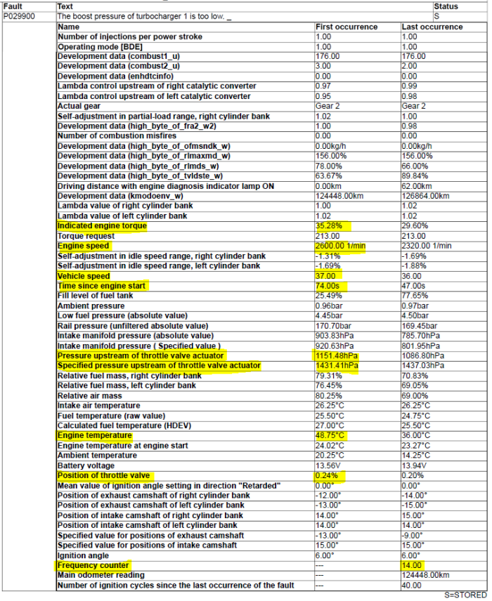
In the freeze frame data we found one value that seemed to be related to the fault code description. The pressure upstream of throttle valve actuator was at 1151.48 hPa, but the specified pressure value was 1431.41 hPa. This told us that the vehicle was producing 280 hPa less boost than requested. Looking at vehicle speed, coolant temp, time since start, engine torque and throttle position helped us to determine what conditions we are going to have to drive the vehicle under to simulate the failure on our road test later.
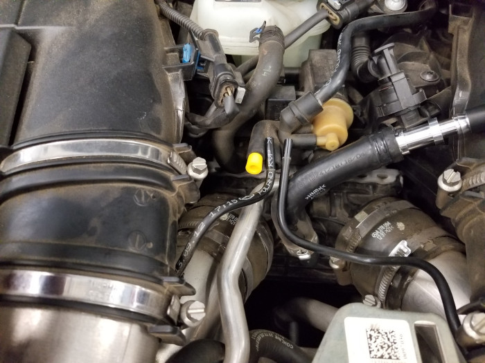
Here are some technical details of the boost control system on the M278 engine. Firstly, it is a bi-turbo V8 engine where both turbochargers are fed via exhaust manifolds on their respective sides. The turbochargers use vacuum generated by a vacuum pump and a reservoir to control the wastegate actuators. The vacuum is supplied via one boost pressure transducer that is duty cycle controlled and tees off to both boost control actuators on turbochargers. With manifold vacuum supplied, the wastegates are both closed via the wastegate control actuators generating boost pressure. If a vacuum leak occurs or the engine management control module wants to reduce power output, the vacuum is released and spring pressure in the wastegate control actuators opens up the wastegates.
We followed all suggested test steps with no failures detected.
Check component ‘Y77/1 (Boost pressure positioner)’ by means of actuation.
The actuation was OK.
Possible cause and remedy
End of test
Since the suggested test steps did not lead to any failures, we drove the vehicle with our Xentry diagnostic tools under same conditions as the freeze frame data listed. All values seemed logical and no fault codes were set. The problem seemed to be intermittent and so the fault code was not easily set. It was time to get creative using the PicoScope and see what kind of guided test we could fabricate to compare the turbocharger's output to that of another engine without any performance issues. To create boost we had to have a load on the engine. This could be accomplished by doing a short power brake in the stall. Next thought was to open both wastegates then try and close them one by one, monitoring the pressure build up before the throttle actuator. To do this we had to:
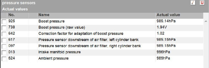
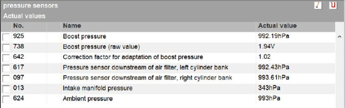
The PicoScope was hooked up to: charge air port via pressure transducer, manifold pressure sensor signal wire and charge air pressure sensor signal wire upstream of turbocharger.
Next we needed to power brake the vehicle safely, with the service brake, emergency brake and tire chocks applied. We held the engine speed at 1800 rpm and plugged one turbo wastegate vacuum line for three seconds then removed and plugged second turbo wastegate vacuum line for the same amount of time. Using a two second per division setting on PicoScope we were able to record both turbocharger waveforms on the same frame. There was an obvious difference when comparing the turbo output left to right.
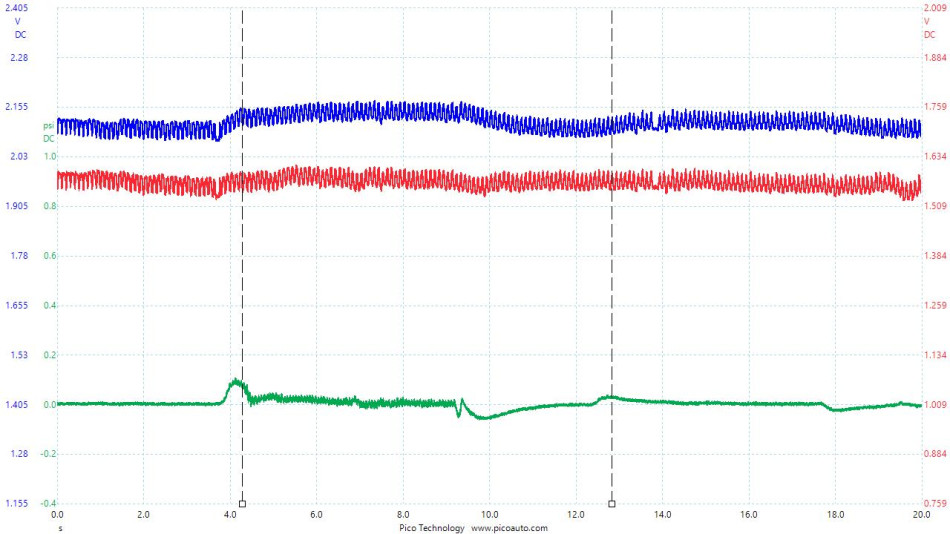
With the lowpass filter function set to 30 Hz for both pressure sensors, and amplifying the signal 8 times, it was easier to see the pressure sensor's reaction to the boost pressure. The first marker shows the left turbo building up pressure and the second marker shows the right turbo building up less pressure.

Zooming in on the pressure transducer reading you can see the difference side to side even better. The right side turbocharger is not building up as much pressure indicating the wastegate actuator on the turbocharger is not fully closing or the wastegate itself has a mechanical defect causing it to not fully seat. Comparing the movement of the arms side-to-side leads us to removing the turbocharger to inspect the wastegate.
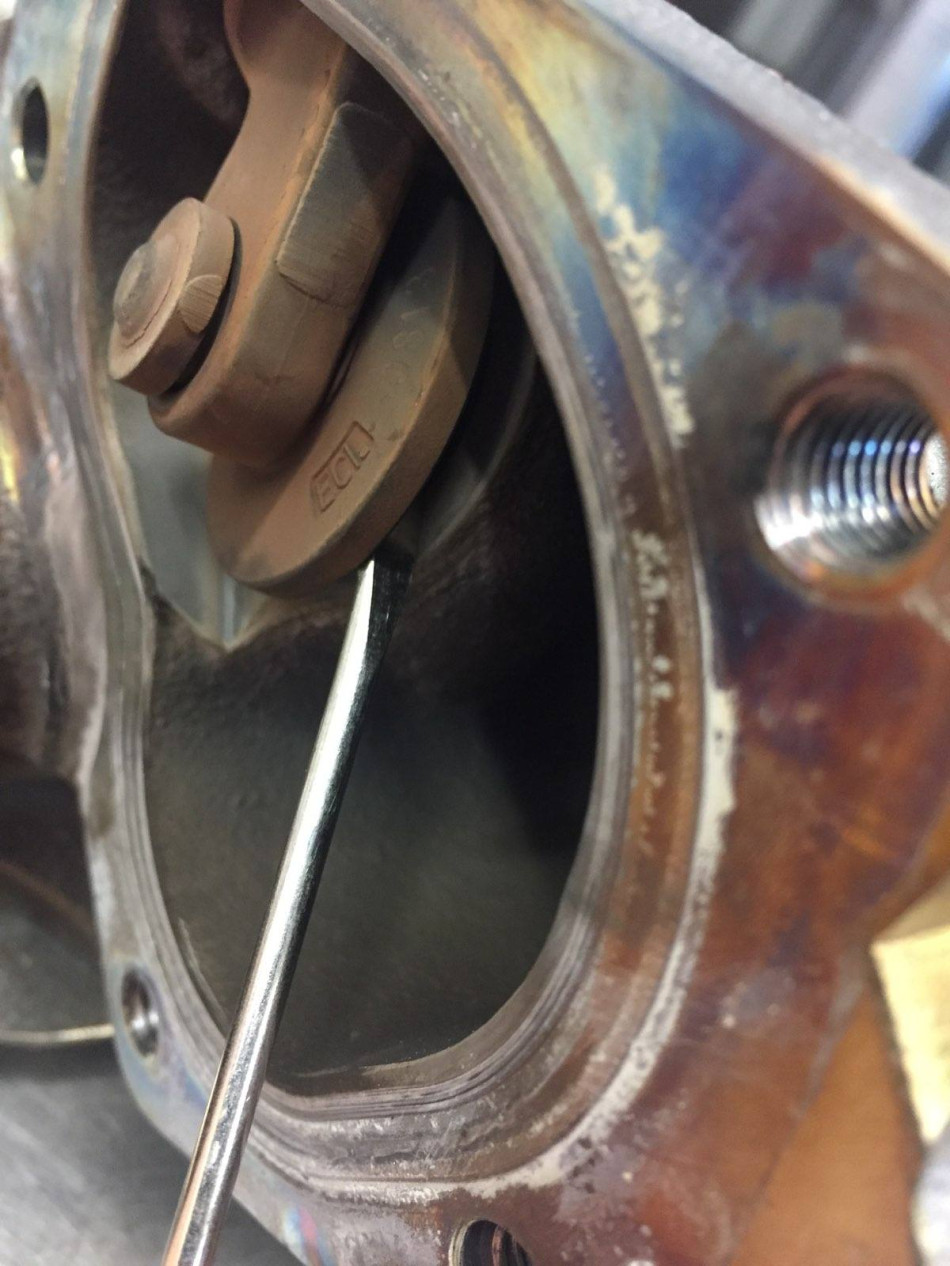
With the turbocharger removed we could see the wastegate bushing was completely worn out causing it not to seal properly. This 30 minute PicoScope test created a simple way of confirming or eliminating a possible wastegate issue on the turbo. It also isolated which turbocharger had a failure saving the shop from replacing both units. In this case we replaced the right-side turbo assembly.
To have a known good pattern we decided to perform the same test on a known good vehicle. You can see below the patterns are identical from the left and right turbochargers.
Rick Rowley
May 01 2018
Scott, awesome diagnostics! Will see you soon for Pico training @ Long Beach.


