PicoScope 7 Automotive
Available for Windows, Mac, and Linux, the next evolution of our diagnostic scope software is now available.
Automotive guided tests
Library of examples on how to perform tests when using PicoScope.

Training
Our collection of training videos, articles, guides and information on training courses.

Waveform library
The Waveform Library is a global database of waveforms uploaded by PicoScope users.

Case studies
Real-life case studies show how the professionals use PicoScope to diagnose vehicle faults.

A to Z of PicoScope
Detailed description of various PicoScope software and hardware features.

Videos
Training resources and demonstrations on PicoScope and the Automotive Diagnostics Kit.

Newsletter
Archive of our monthly Automotive Newsletters.

Documentation
Download manuals, brochures, posters, and training materials.

Reviews and awards
Accolades for the preferred diagnostic tool for service centers and vehicle manufacturers.

| Vehicle details: | Triumph Bonneville 1200 |
| Year: | 2018 |
| Symptom: | |
| Author: | Ben Martins |

WPS500X Pressure Transducer
*At Pico we are always looking to improve our products. The tool used in this case study may have been superseded and the product above is our latest version used to diagnose the fault documented in this case study.
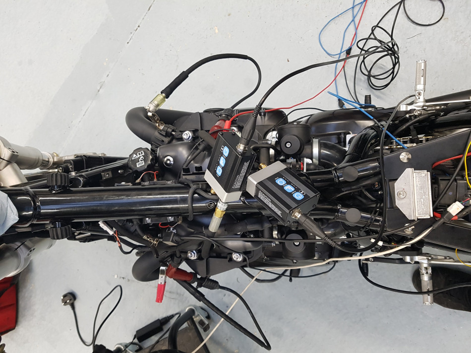
We were recently asked to assist with the development, set-up and ultimately the tuning of a rather unique motorcycle. The request turned out to be a fascinating adventure into Motorbikes!

Not ever having much to do with bikes the thought of looking at a custom build with a number of upgrades couldn’t be passed up. The bike in question is being built specifically for a client but is a first of its kind and as the first one, inevitably, there were some gremlins. With a custom ECU, custom wiring loom, a 270° crank arrangement and two different fuelling strategies things were not going to be straight forward.
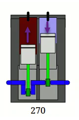
Firstly what is very important here is to establish what a 270° crank actually is. With a 270° crankshaft there is an offset between the two pistons of 90°. Below is an overview of the ignition events at TDC in a two cylinder engine with a 270, 180 and 360 degree crank.
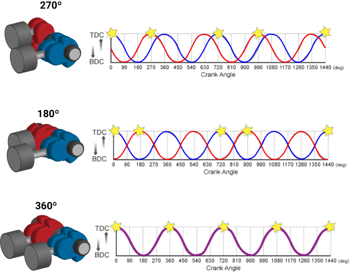

The 180° crank is one we are familiar with and if it had 4 cylinders this would have had the ignition events at 360° and 540°.
With the 270° setup we have a piston at TDC after the compression stroke then 270° later the second piston is on TDC after its compression stroke. Then there is a gap of 450° before the first cylinder is back at TDC giving the full 720°.
The primary advantage of a 270° crank arrangement is to get the best possible secondary engine balance from a parallel twin engine producing a power delivery which resembles that of a 90° V-twin.
It is important to understand the 270° arrangement as the rest of the investigation involves a lot of degrees!
I was intrigued at this point to see what differences you could see between this type and a conventional crankshaft arrangement, so the first thing I looked at was relative compression.

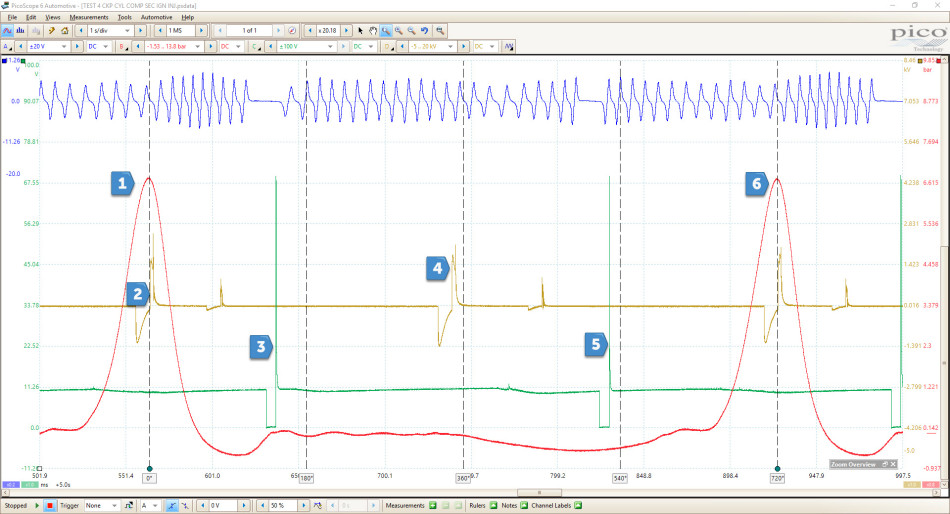
To start with I was really surprised to see that the initial in-rush current to the starter motor over ranging at 500 A. I would never have expected to see a two cylinder engine pull this much current trying to get it turn over but then I was assuming it was because it’s a 2 cylinder. It’s still a 1200 cc, lesson number one learnt! The next lesson was looking at the relative compression waveform which if you were looking at this without understanding the type of crankshaft this engine has; you would have told me that there was a lack of compression. However, when you start placing the rotation rulers into the capture you can start to see that actually this is correct.

I’ve overlaid the image from the crank rotation table onto the relative compression capture. We have compression event at one and two which is seen in our current but then the gap at three of 450° before the next compression event. Now I’m sure you’ve already noticed that there is a slight increase in current at approximately 450°. One theory would be that because both pistons are in the bottom half of the cylinder there is a reduction in speed in the crankshaft approaching and passing BDC and as no combustion has taken place in the other cylinder there is nothing to help keep the inertia in the crankshaft to get the piston back up towards TDC. In order to get the piston to start moving back up on the exhaust stroke of the second piston, the engine may require the starter motor to provide more effort which will overcome this. If anyone knows or has another suggestion then please share your thoughts.
For our next step we decided to use two WPS500x in-cylinder to understand why there would be a slight increase in current draw from the starter motor without a piston on a compression stroke.
Something that I was not aware of was the cylinder layouts in bikes. For this particular engine cylinder 1 is regarded as the left hand cylinder if you were sitting on the bike but the ECU uses cylinder 2 as the primary cylinder and references ignition and timing from this, just to make things a little more confusing, if it wasn’t already! From this point on we will refer to cylinder 2 as the primary cylinder as the majority of our measurements will be with reference to cylinder 2.
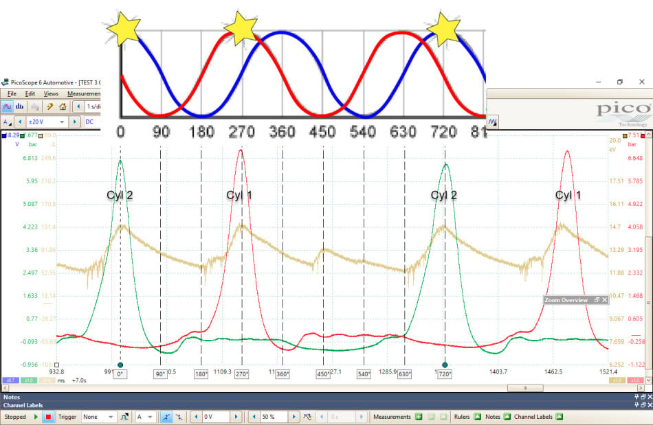
After cranking the engine we begin to see the true representation of the 270° crank. We added ignition sync as well as the CKP sensor to make use of the four channels and to identify the cylinders we were referring too.
To help keep the screen from looking too cluttered, I’ve removed the CKP sensor and the ignition trace as I’m only really interested in ensuring engine is mechanically ok. Again, I have included the crank rotation graph to establish the piston position in relation to crank rotation.. As you can see the compression peaks meet exactly with the peak current draw . Then there is this small current increase at 450°. We can now see the two piston positions at 450°. Cylinder 1 is on its intake stroke. No deep drop in pressure here which could result in an increase in current draw due to the cylinder creating a stronger vacuum. Cylinder 2 is on the exhaust stroke and any restriction in the exhaust would also see an increase in pressure and therefore an increase in current, however, no exhaust restriction is present.
So back again to the theory earlier where we assume there is a slowdown in the crank due to engine. This is my assumption as I can’t see anything else mechanically, that would be a problem. Please share your thoughts; let’s open it up for discussion.
Next we looked at ignition and injection events.
On initial start-up this engine runs something called batch firing. After starting the system switches to a standard sequential arrangement.
Batch firing is where the ECM sends both an injection and an ignition signal every 360° of crank rotation.
The usual for a four stroke would be every 720°.
The reason behind batch firing is so the engine can start from cold having the best possible chance of firing and once running can switch to standard fuelling.
For these measurements the ECM was programmed to fire the ignition exactly at TDC. This allowing us to make sure that the spark event we have is the correct event when the ECM switches from Batch to Sequential and from here make any adjustments to ignition advance.
This is where I was pleased that I had Chris Wells from X bikes on-hand as he has the appropriate experience and tools to adjust and upload custom settings to a programmable ECM.
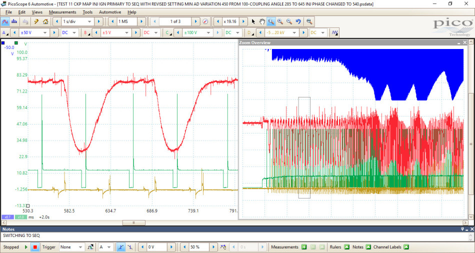
From the waveform we can see the ignition event occurring directly at TDC. We then see an injection event happening as the piston is still travelling down the bore and the exhaust valve is opening. Next we have another ignition event at 360° during the period when the exhaust and inlet valve are overlapping. Then as expected an injection event takes place during the inlet stroke and finally we get the ignition event happening 720° after the first compression event. Here by looking at points 3 and 4 we are seeing this batch firing which is required to get the engine to start. Once started the system switches to the sequential fuelling strategy we normally associate with the 4-stroke cycle.
The point at which the fuelling strategy switches is based on MAP sensor and RPM data. Once the MAP sensor voltage crosses a certain point and when a certain RPM has been met, then the ECM will switch to sequential. These points can be adjusted using the software and then uploaded to the ECM. Happy that mechanically the engine was we removed the WPS500X to take a look at the MAP sensor.
This is a standard 5 V three wire sensor with a constant feed, earth and signal circuits.
The interesting thing behind the map sensor in this engine is its purpose. Instead of using a camshaft sensor for engine position, the ECM monitors the position of the engine based on the intake manifold pressure.
I mentioned earlier about the cylinder layout and the fact cylinder 2 is the primary cylinder where ignition and injection are referenced from, therefore the MAP sensor is placed so it can monitor the pressure from the primary cylinder. When the cylinder is at the BDC on the intake stroke it has drawn its maximum volume of air into the bore before compression. At this point the ECM registers the cylinder position in order to adjust the fuelling and ignition events. All the captures below are from cylinder 2 or the ‘Primary’ cylinder.
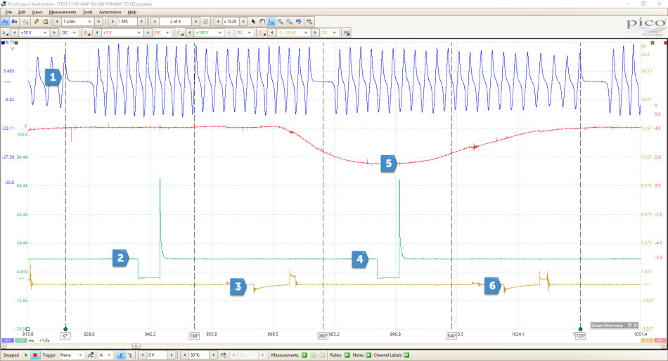
From the above waveform we can now see the MAP sensor confirm a change in inlet manifold pressure. This was all done at idle so we have a partially closed throttle butterfly which results in a decrease in manifold pressure as the inlet valve opens and the piston moves down the bore. At the same time we see an injection event taking place which would be correct, we want the air and the fuel to mix together as the piston is travelling down before coming back up on the compression stroke. This is all normal apart from the extra ignition and spark event that is taking place at points 2 and 3 caused by batch firing. The bike will run in this condition and but will have the tendency to backfire if throttle is increased which would make sense considering fuel is being injected around the exhaust stroke and an ignition event is also taking place.
Whilst the bike was running we altered the threshold that the ECM needs to see from the MAP sensor in order to switch to sequential. As soon as it did so the bike cut out and stopped. Looking back over the capture we found the cause of the issue.

As you can see we have the conventional 1 injection, 1 ignition event per 720° of rotation for the four stroke cycle. What we notice though is the injection event is completely in the wrong place, in this case it is during the Power stroke. Ignition is in the ball park although probably too far advanced but would probably ignite the mixture enough to get it to run. Now we move onto the next brain melting phase, something called Coupling Angle.
This again is an adjustable figure which can be programmed with the mapping software. This next bit is still a little hazy for me – but here is my understanding:
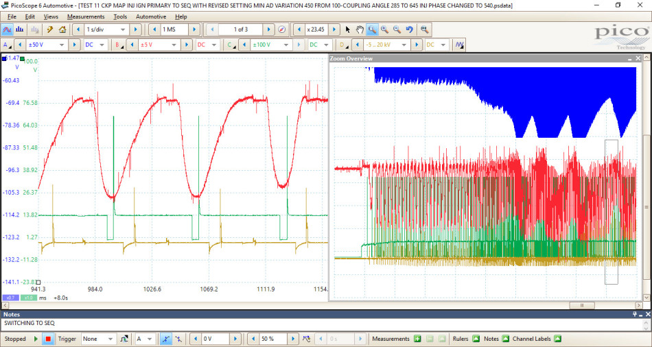
The coupling angle is the point that the ECU determines the position of the cylinder based on the position of the CKP sensor. Instead of being based on 1 revolution it looks at two therefore the 720° we have for the 4-stroke cycle. We were currently set to 285° which means the ECM will set the point at which the piston is at TDC on its compression stroke in relation to distance after the missing teeth on the crankshaft pickup ring, in this case 285°. If we take the above waveform the injection event is taking place nearly 360° too early. Carrying out a measurement between the injector at point 3 in the above waveform and the lowest reading from the MAP sensor during the intake stroke is 360°. This will and can change but by looking across a number of different positions in the capture, this is the number that we keep coming back to. With this in mind the decision was made to adjust the coupling angle to 645°, 360° on from the original 285°.

Now things are starting to look a lot better! We have an injection event taking place during the intake stroke and then an ignition event which occurs 180° when the piston will be a TDC. We still have our ignition timing set to 0° which would result in the event taking place directly at TDC. All this can be adjusted use the mapping software. At this point the Bike started and was running a lot smoother. We also noticed that it was a lot quicker at moving to sequential from batch after initial start-up. Some slight adjusting with the ignition timing and adjusting the fuelling there was a bike that would start, idle and accelerate.
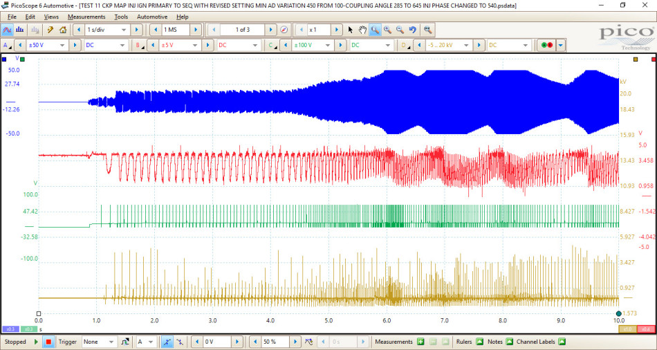
I know the above captures look a little messy but I wanted to give an overview of the engine starting, at idle and then with RPM increase. Using the crank sensor change in amplitude we can see all of these different stages of engine condition. What is interesting to see is the output of the crankshaft sensor. As the sensor is an inductive crank position sensor, when the engine speed increases so will the output amplitude. In the above capture we were over ranging at ±50 V at approximately 6000 rpm. Most bikes will rev a lot more than this, so I think in the future with a running bike it would be important to make sure you allow for at least ±100 V.
There’s a lot to take in from all of this and the fact we have seen exactly what is going on with an engine with a 270° is something I won’t be forgetting in a long time! One thing that was particularly useful was being able to confirm engine position using WPS500X. I know not everyone will have the luxury of having two WPS500X to play with but with a reference to ignition and crank you will be able to achieve the same thing by using reference waveforms. With this we could physically see the 270° crankshaft operation and its effect on compression. Not only was WPS500X used for compression and engine position but also we could confirm that the MAP sensor operation was correct. Watching the voltage change when the piston was on the intake stroke was evidence that the MAP sensor was detecting a change in pressure during the intake stroke which with this engine and ECM was vital as it is used for engine phasing.
Also from the time spent with this bike I think it shows just how flexible engine management programming can be. Even when I think of the software updates we used to do in the dealership, I never appreciated until now the amount of control and adjustment that can be made with modern ECM to get the most out of the engine without having to upgrade any parts. This finite control which can be used to increase power, efficiency or emissions is outstanding and can now often be done over OTA (over the air), but if slightly wrong can cause so many problems. I must take this opportunity to thank Chris Wells for the opportunity to look more into this world of programming and motorbikes but also the fact this bike had a 270° crankshaft. His experience and knowledge was very important to help understand what was going on! I must also thank Mr Steve Smith for his ongoing support and for his input during this adventure – in his words “we live and learn together” and never were truer words spoken!
Rhianne
March 14 2021
Excellent article, thank you!
Scott Thomas
September 01 2018
Most Bosch PFI systems inject on the Exhaust stroke, not the intake stroke. This is typically avoided. Injecting on the Exhaust stroke allow for improved mixture vaporisation.