PicoScope 7 Automotive
Available for Windows, Mac, and Linux, the next evolution of our diagnostic scope software is now available.
Automotive guided tests
Library of examples on how to perform tests when using PicoScope.

Training
Our collection of training videos, articles, guides and information on training courses.

Waveform library
The Waveform Library is a global database of waveforms uploaded by PicoScope users.

Case studies
Real-life case studies show how the professionals use PicoScope to diagnose vehicle faults.

A to Z of PicoScope
Detailed description of various PicoScope software and hardware features.

Videos
Training resources and demonstrations on PicoScope and the Automotive Diagnostics Kit.

Newsletter
Archive of our monthly Automotive Newsletters.

Documentation
Download manuals, brochures, posters, and training materials.

Reviews and awards
Accolades for the preferred diagnostic tool for service centers and vehicle manufacturers.

| Vehicle details: | Vauxhall Corsa |
| Year: | 1999 |
| Symptom: | Engine misfire |
| Author: | Nick Hibberd | Hibtech Auto-Electrical Diagnostics |
Ordinarily I wouldn’t have given this the time of day had it not been for an unusual recorded trace, which I felt would be interesting to share. The eventual cause of the fault was… you’ll have to see it to believe it. The vehicle was a 1999 Vauxhall Corsa into which someone had shoehorned a V6 lump. This particular production run also came with a second instrument cluster hack: sawed (literally!) into the passenger dashboard and providing amusement for onboard participants, no doubt. Quite a little cherub.
The complaint was that at high rpms the engine would stumble and misfire. Release the throttle to idle, and it fired on all six again. The problem didn’t appear temperature- or load related, and I could recreate the complaint in the workshop, which is always helpful. Checking the engine system with the scan tool proved a waste of time as no socket connection was wired up. All things considered, I made up my mind to make one hook-up with the scope and if that didn’t point me in a clear direction then I was handing back the keys.
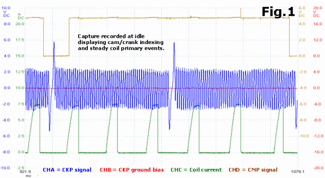

You will, no doubt, have spotted the erratic coil primary events, which are a serious contributing factor to the engine’s stumbling. There isn’t much right about the primary events during the fault period: primary dwell is sometimes too short, sometimes too long, sometimes overlapped, and sometimes missing altogether. The ECM is clearly struggling to maintain correct ignition timing.
Not least is the odd CKP signal momentarily hanging high immediately after the sync trigger. All the captures recorded during high rpms displayed the same unusual signature after the sync, yet the remaining rotor signals generally appeared normal and acceptable. In fact, those with a keen eye may be able make out the early stages of this signature back in the idle capture, Fig.1.

With different issues to deal with, I find it best to break the problem down and prioritise the concerns. Very often when one root cause is found it usually explains other related issues. For me the most important anomaly here is the unusual drift in the CKP signal, and considering this critical signal is used to determine each ignition point, there’s a good chance to eliminate multiple issues following one test plan.
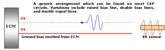
A bad CKP sensor? To very briefly summarise the variable reluctance (VR) sensor operation: it can only react to what it sees. During our signal drift the sensor is still capable of producing a recognisable sine wave, and its general operation is further confirmed by the remaining rotor teeth being displayed as normal, centred on the ground bias. Simply put, the VR sensor does not get to choose what bias voltage the generated signal rests on. This is entirely left to external factors within the management system design. For the moment, a faulty CKP sensor is low down on the list for this root cause.
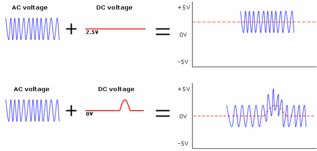
A bad trigger wheel? This is one which provoked the most thought. It does seem evident that our unusual signature only appears in one place on the trigger wheel, each and every time. A bad spot on the wheel would certainly create a repetitive pattern and throw the signal out in one way or another. Thus, so far, all the boxes are ticked. But we have to be clear what “fault” we are chasing. The fault lifts the entire waveform so that its negative peaks are above the bias voltage (in this case, zero volts), something that no defect in the trigger wheel could cause. This was not a mechanical problem: this was electrical in origin.
A problem with the CKP electrical circuit? This now is most likely, although at this point in the investigation I could only describe the fault as something pulling the signal line towards a positive potential: a circuit leak perhaps. We can eliminate a problem with the ground bias as this remains steady throughout the fault.
With a theory in place, the next step was to verify circuit insulation all the way back to the ECM. I followed the engine harness routing through the firewall and down to the driver’s kick panel, where I found the ECM rattling loose behind a trim. The test plan was to disconnect the ECM connector and check continuity between the CKP circuit and other connector terminals, hopefully resulting in some abnormal insulation readings. I didn’t get that far…
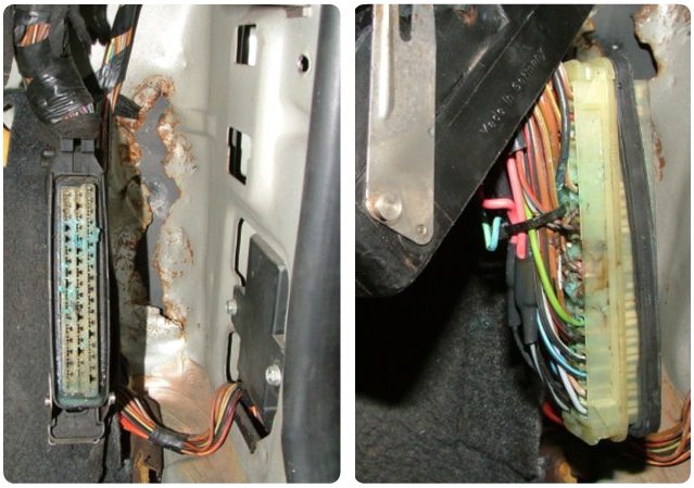
The ECM connector had suffered severe water ingress and was well on the way corroding the ECM male pins too. With this degree of severity and a maze of cross-circuit voltage leaks it’s impossible to isolate the track our CKP signal was taking, except to say it had a lot of choice.

The voltage kick we normally see around the sync gap was, I suspect, a contributing factor to our unusual signature, leaving residual voltage after the peak leaking into the corrosive chaos and hanging on the end of the peak. Scrutinising the captures further revealed signs of the signal wavering at other points too. There’s a lot happening here and it would certainly have manifested with other issues in the surrounding circuits producing some problems of their own. A real mess.
The subtle wheel arch modification was likely created to accommodate the bulky ECM and connector not original to this car. Once discovered, this butchery justified my apprehension at the beginning. It’s OK though: the plastic wheel liner will stop any water from getting in!
Download the PicoScope data files of the waveforms featured in this article:
| |
V6 Corsa bad waveform.psdata | 2 MB |
Ralph Thibodeau
July 30 2012
nicely done keep them comming there great!!!
Peter Litchfield
November 07 2010
Excellent, very well done
Hank
September 06 2010
Also noticed this in a trade magazine, given to us by one of our suppliers, excellent diagnosis though !!! well done indeed, but as u said earlier curiosity gets the better of us all !!!
Kenneth Webb
August 23 2010
It’s great to see these problems before and after the repair, along with the pictures.
As an automotive faculty it’s great to have samples like this to show the Apprentices.
Too many in our trade think that all they require is a scan tool, not true the scope is the BEST tool to date to assist in rapid repairs.
Keep up the great work.
Stephen Pender
August 22 2010
Glad to see curiosity got the better of you as it does us all and we just have to find that root cause. Well done and appreciate the article
Phil Lynch
August 07 2010
Very intresting I would not have picked up this fault from the waveform shown and probably sent it away. Certainly food for thought. Thanks.
If we learn a little every day we will understand more.
Paul Lane
June 30 2010
Yet again Nick another excellent, well documented diagnostic procedure, which made a very interesting educational read.


