PicoScope 7 Automotive
Available for Windows, Mac, and Linux, the next evolution of our diagnostic scope software is now available.
Automotive guided tests
Library of examples on how to perform tests when using PicoScope.

Training
Our collection of training videos, articles, guides and information on training courses.

Waveform library
The Waveform Library is a global database of waveforms uploaded by PicoScope users.

Case studies
Real-life case studies show how the professionals use PicoScope to diagnose vehicle faults.

A to Z of PicoScope
Detailed description of various PicoScope software and hardware features.

Videos
Training resources and demonstrations on PicoScope and the Automotive Diagnostics Kit.

Newsletter
Archive of our monthly Automotive Newsletters.

Documentation
Download manuals, brochures, posters, and training materials.

Reviews and awards
Accolades for the preferred diagnostic tool for service centers and vehicle manufacturers.

Modern emission regulations have forced tighter control of engine management systems throughout all engine speed and load ranges. The traditional oxygen sensor could accurately detect the stoichiometric air-fuel ratio at 14.7:1 (Lambda 1.0) with an output of approximately 450 mV. However, beyond the stoichiometric point, the traditional oxygen sensor would output either a rich signal (900 mV) or a lean signal (100 mV) with no indication of just how rich or how lean. The engine management would, therefore, compensate by adjusting the fuelling (closed loop control) back and forth (rich/lean) in an attempt to maintain the correct stoichiometric air-fuel ratio. The traditional oxygen sensor could therefore only operate accurately in a very narrow range of air fuel ratios (14.7:1), hence the name Narrowband oxygen sensor.
The demand for increased accuracy, faster response times and reliability has seen the redevelopment of the narrowband oxygen sensor to the industry standard oxygen sensor utilised today across all manufacturers, the Wideband oxygen sensor.
The wideband oxygen sensor is often referred to as a broadband sensor or air-fuel ratio sensor (AFR sensor) and can be installed to both petrol/diesel engine vehicles.
The name wideband is derived from the sensor's ability to accurately detect the air-fuel ratio across a wide spectrum from 10:1 to 20:1 (20:1 being ambient air) unlike the narrowband sensor's ability to detect only the stoichiometric ratio of 14.7:1.
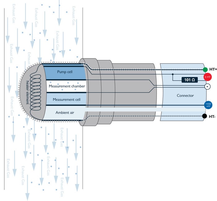
The wideband oxygen sensor does, however, incorporate a proportion of the operational characteristics of the narrowband sensor in the form of a Measurement cell. The measurement cell is exposed to atmospheric air on one side (reference air) and exhaust gas oxygen in the Measurement Chamber on the other. Assuming the oxygen content in the measurement chamber is maintained at a specified level, 450 mV is output from the wideband oxygen sensor measurement cell to the PCM (Channel A).
Maintaining the correct oxygen level in the measurement chamber is paramount to ensure the voltage output from the measurement cell remains as close as possible to 450 mV throughout all fuelling conditions. This is achieved by the Pump cell.
The characteristics of the Pump cell are such that depending upon the amount and direction of current flow through the Pump cell (PCM controlled), oxygen can be pumped into or out of the Measurement chamber, so maintaining 450 mV output of the Measurement cell.
The current flow through the Pump cell is therefore used a direct and accurate indication of the air-fuel ratio across a broad spectrum as a result of the oxygen content in the exhaust gas.
Control of the heater element of the broadband oxygen sensor is critical to the correct operation of the sensor. Oxygen sensors that remain unheated will eventually “clog” and require replacement, while electrochemical reactions inside the sensor that ensure the transportation of oxygen and the generation of voltages simply cannot take place if the oxygen sensor temperature is not maintained.
Oxygen sensor heater element
Should the oxygen sensor heater element resistance value obtained in Step 1 differ from the specified value (4.5 Ω approximately at 20 °C) replace the oxygen sensor.
Check for short circuit between pins 3 and 4 and the remaining pins 1, 2, 5, and 6. >1 MΩ.
Check for short circuit between pins 3 and 4 and the outer metal casing of the oxygen sensor (Chassis ground) > 1 MΩ. If a resistance value lower than 1 MΩ is obtained, replace the oxygen sensor.
Calibration resistor circuit
Should the calibration resistor value obtained in Step 2 differ from the specified value, remove the breakout leads (oxygen sensor and vehicle battery disconnected) and measure the resistance of the calibration resistor inside the oxygen sensor connector between terminals 6 and 2. It should be approximately 100 to 110 Ω (Fig 7). If the value obtained falls outside of the specified range, replace the oxygen sensor.
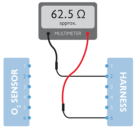
If the oxygen sensor calibration resistor value is found to be correct, measure the resistance value of the engine wiring harness (oxygen sensor and vehicle battery disconnected) between terminals 6 and 2. It should be approximately 62 Ω (Fig 8).
If the value obtained differs from the specified value, inspect and test the wiring harness between the oxygen sensor connector and the PCM for open or short circuits to chassis ground, for short circuits between terminals 6, 2 (battery disconnected) and for short circuits to battery positive (with battery reconnected and ignition off). If the results obtained confirm the engine harness to be serviceable then the PCM is suspect.