PicoScope 7 Automotive
Available for Windows, Mac, and Linux, the next evolution of our diagnostic scope software is now available.
Automotive guided tests
Library of examples on how to perform tests when using PicoScope.

Training
Our collection of training videos, articles, guides and information on training courses.

Waveform library
The Waveform Library is a global database of waveforms uploaded by PicoScope users.

Case studies
Real-life case studies show how the professionals use PicoScope to diagnose vehicle faults.

A to Z of PicoScope
Detailed description of various PicoScope software and hardware features.

Videos
Training resources and demonstrations on PicoScope and the Automotive Diagnostics Kit.

Newsletter
Archive of our monthly Automotive Newsletters.

Documentation
Download manuals, brochures, posters, and training materials.

Reviews and awards
Accolades for the preferred diagnostic tool for service centers and vehicle manufacturers.


20 A / 60 A DC (low amps) current clamp

Premium Test Leads: Set of four leads 3 m (TA125 - TA128)
*At Pico we are always looking to improve our products. The tools used in this guided test may have been superseded and the products above are our latest versions used to diagnose the fault documented in this case study.
The purpose of this test is to evaluate the operation of the Bosch LSU 4.2 6 wire oxygen sensor (pre-catalyst) in relation to the air-fuel ratio using the volt-drop method.
Note: This guided test makes use of the PicoScope 4425 automotive scope from Pico Technology and must not be used as guidance for any other piece of test equipment, whether manufactured by Pico Technology or not. Connecting any other equipment may result in damage to that equipment or to vehicle components.
The Bosch part numbers covered by this guided test are:
Note: The correct operation of the oxygen sensor depends on:
The following procedure assumes that the conditions mentioned above are all in order and the oxygen sensor is functioning correctly. Any failures identified with the operation of the oxygen sensor while conducting these tests does not necessarily indicate a fault with the oxygen sensor itself.
Often the oxygen sensor will display operational characteristics that are inconsistent due to fuelling or mechanical errors. The results obtained are therefore symptoms of underlying conditions and not the cause.
It is, therefore, essential to evaluate the engine mechanical condition and management system BEFORE condemning the oxygen sensor. All numerical readings quoted in this help topic are typical and not applicable to all engine types.
Before taking any measurements with the PicoScope, you need to measure the resistance values of the calibration resistor circuit and the oxygen sensor heating element. Should either of these measurements differ from the specified value, please see the Troubleshooting section at the end of this technical note.
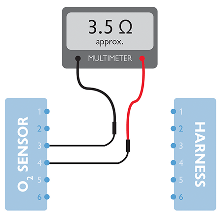
How to test the oxygen sensor heater element
Value obtained: Approximately 3.5 Ω @20 °C.
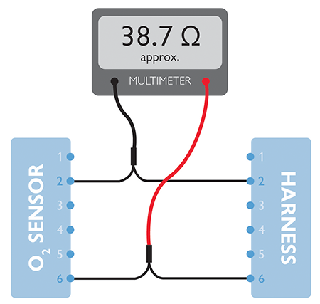
How to obtain the oxygen sensor calibration circuit resistance value
A calibration resistor is installed into the oxygen sensor connector at manufacture to ensure a superior accuracy of the sensor across all air-fuel ratios. The resistor/connector is, therefore, specific to the sensor and cannot be replaced.
Note: Terminal numbers are stamped on the body of the oxygen sensor connector.


Once the resistance values have been confirmed the scope can be connected to evaluate the oxygen sensor operation: Connect three test leads to Channel A, Channel B and Channel C on the scope. Connect the blue test lead on Channel A to the breakout lead connected to terminal 1 of the oxygen sensor, and the black ground lead to the breakout lead connected to terminal 5 of the oxygen sensor (here we acquire the Measurement cell voltage). Connect the red test lead on Channel B to the breakout lead connected to terminal 6 of the oxygen sensor and the black ground lead to the breakout lead connected to terminal 2 of the oxygen sensor (here we acquire the Pump cell voltage). Connect the green test lead on Channel C to the breakout lead connected to terminal 3 of the oxygen sensor and the black ground lead to the breakout lead connected to terminal 4 of the oxygen sensor (here we acquire the oxygen sensor heater control voltage). Connect the 20/60 amp current clamp to Channel D of the scope, Zero and link the clamp around the breakout lead connected to terminal 4 of the oxygen sensor (here we acquire the oxygen sensor heater current). Note: Check for correct orientation of the clamp to enable the scope to read a positive current value. Run your scope software by pressing either the spacebar on your keyboard or the Go button in PicoScope. Crank and start the engine, and allow idle speed to stabilise. Noise may be present on your waveform during the warm-up period of the oxygen sensor. This is an operation characteristic and not a fault. With the engine at the correct operating temperature carry out numerous momentary Wide Open Throttle (WOT) snap tests while monitoring the signal on Channel B (Pump cell voltage). Snap throttle tests will allow the air-fuel ratio to momentarily increase then decrease to reveal the switching function of the Pump cell. Press the Stop button in PicoScope to halt the capture to enable waveform analysis.

Refer to vehicle technical data for specific test conditions and results.
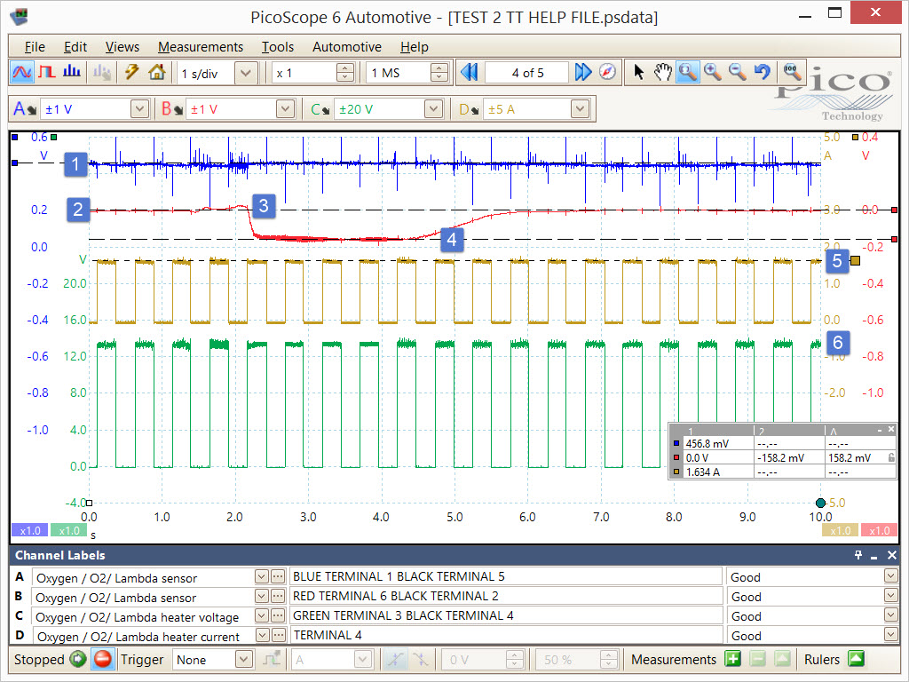
Typical values (engine at correct operating temperature):
Engine idling: Oxygen sensor Measurement cell voltage should remain near stable at 450 mV regardless of engine fueling condition.
Engine idling: Oxygen sensor Pump cell voltage will rise and fall depending on the level of oxygen content detected in the exhaust system. Under normal running conditions, the voltage will remain fixed at 0 V indicating the correct stoichiometric air fuel ratio of 14.7:1 (lambda 1.0) The Pump cell voltage and current values have the following characteristics:
WOT snap test: Indicates a small rise in Pump cell voltage at the point of WOT (+ 30 mV) as the oxygen content in the exhaust system falls due to acceleration enrichment (oxygen is pumped into the Measurement chamber).
Over-run fuel cut: Indicates a fall in Pump cell voltage (-158 mV) during the engine over-run fuel cut condition. The oxygen content in the exhaust system will therefore increase. (Oxygen is pumped out of the Measurement chamber.)
The switching of the Pump cell voltage during WOT and over-run confirms the oxygen sensor to be performing correctly. The response to acceleration and deceleration of the engine should be near instant confirming the oxygen sensor response time to be efficient. The activity of the Pump cell is normally measured using a milliamp clamp rather than recording the voltage. Given the resistance value of the Pump cell circuit is known from the test carried out in Step 2 above, we can convert the recorded Pump cell voltage to a current value using Ohm's law (Current = Volts / Resistance) so removing the need for a milliamps clamp.
See (Figure 6) where a math channel is utilised to carry out this calculation and display the Pump cell current as an additional waveform.
Engine running: Confirms the maximum heater circuit current (1.6 amps). The heater current waveform should mirror the PWM signal seen at point 6.
Engine running: Confirms good PWM control (> 2 Hz) of the oxygen sensor heater element as the voltage is switched from 0 V to 13.5 V approx. The sensing element within the oxygen sensor requires a minimum operating temperature of 300 °C and will need to be controlled throughout the operation of the engine to ensure efficient functioning while maintaining the reliability of the heater element.
Note: There may be occasions where the PWM control of the oxygen sensor is halted by the PCM (during initial WOT). This is dependent on the manufacturer and serves ultimately to improve fuel economy and emissions by reducing the electrical load on the vehicle.
The PCM may also vary the PWM control during the warm-up process to ensure the sufficient dispersion of water/ condensation under various environmental operating conditions.
Waveform capture stopped: The example waveforms above do not directly measure the current flow through the Pump cell but do measure the voltage which will also change in proportion to current flow (Channel B).
Given the resistance value of the Pump cell circuit was measured and confirmed as 38.7 Ω approx. we can incorporate this value into a 5th black math channel to convert the Pump cell voltage measured using Channel B into a current value using Ohm's law: Current = Voltage / Resistance. I = V / R
While the scope collects data from Channel B you will notice a 5th black math channel will appear at the end of each screen capture. By stopping the capture (press the space bar or stop button) the math channel will appear on the screen. Using the waveform buffer you can scroll through your captures and measure the Pump cell current from the maths channel which is directly proportional to the Pump cell voltage.
Measuring the activity of the broadband oxygen sensor using the volt drop method accompanied with Ohm's law removes the need for expensive milliamps clamp to measure tiny current values ranging from 0.5 mA to 3.5 mA.
You can find more information about the Bosch LSU 4.2 broadband oxygen sensor in the online training section on our website.
GT784-2
Disclaimer
This help topic is subject to changes without notification. The information within is carefully checked and considered to be correct. This information is an example of our investigations and findings and is not a definitive procedure.
Pico Technology accepts no responsibility for inaccuracies. Each vehicle may be different and require unique test
settings.
We know that our PicoScope users are clever and creative and we’d love to receive your ideas for improvement on this test. Click the Add comment button to leave your feedback.


