PicoScope 7 Automotive
Available for Windows, Mac, and Linux, the next evolution of our diagnostic scope software is now available.
Automotive guided tests
Library of examples on how to perform tests when using PicoScope.

Training
Our collection of training videos, articles, guides and information on training courses.

Waveform library
The Waveform Library is a global database of waveforms uploaded by PicoScope users.

Case studies
Real-life case studies show how the professionals use PicoScope to diagnose vehicle faults.

A to Z of PicoScope
Detailed description of various PicoScope software and hardware features.

Videos
Training resources and demonstrations on PicoScope and the Automotive Diagnostics Kit.

Newsletter
Archive of our monthly Automotive Newsletters.

Documentation
Download manuals, brochures, posters, and training materials.

Reviews and awards
Accolades for the preferred diagnostic tool for service centers and vehicle manufacturers.


200 A / 2000 A (high amps) DC current clamp

Multimeter Probes

Back-pinning Probe Set

Flexible Back-pinning Probe

Large Dolphin/Gator Clips
*At Pico we are always looking to improve our products. The tools used in this guided test may have been superseded and the products above are our latest versions used to diagnose the fault documented in this case study.
The purpose of this test is to check the command, feedback, and output voltage signals from a Ford-type smart charging alternator.
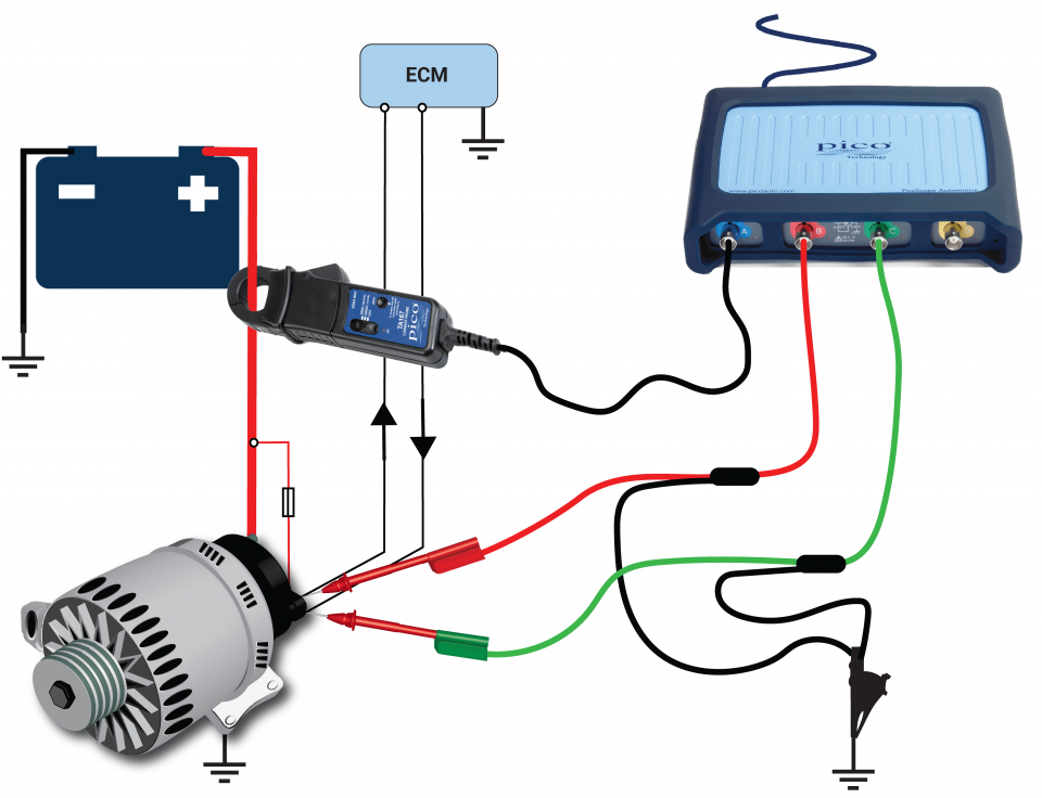
View connection guidance notes.
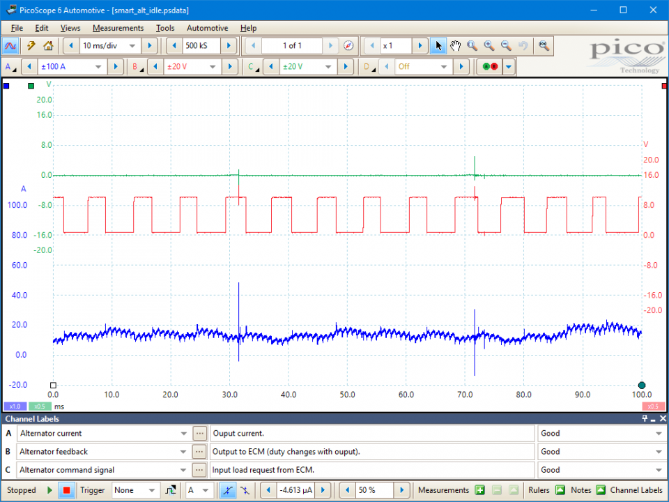
Engine idle, alternator under light load.
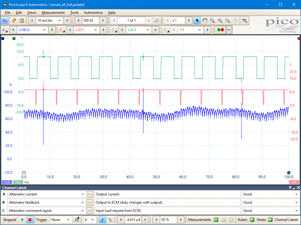
Engine at idle, alternator under moderate load.
These known good waveforms have the following characteristics:
Go to the drop-down menu bar at the lower left corner of the Waveform Library window and select, Alternator command signal.

When the engine is running, an alternator generates electrical energy to supply the vehicle’s onboard electrical systems and replace the battery charge consumed during cranking.
Smart charge systems are able to balance these requirements against the needs of the driver, such as the requirement for maximum torque on hard acceleration, and the need for less engine drag during normal operation, for better fuel efficiency. Furthermore, they can closely manage the battery’s needs, for example by providing a higher charging rate at cold ambient temperatures. This helps to keep the battery in optimum states of charge and health.
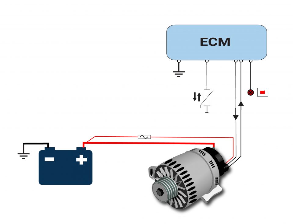
Typically, the Engine Control Module (ECM) controls charging and can vary the charge rate dependent on a number of factors, such as ambient temperature (or battery ambient temperature), accelerator pedal position, electrical loading, and engine speed etc.
The alternator works at maximum capacity only when absolutely necessary. However, in the right conditions, such as after cold cranking in low ambient temperatures, the ECM can increase alternator output to 18 V. Therefore, it is essential that correctly specified batteries are used in these applications [Ford specified silver calcium batteries for their systems].
Conventional lead-acid batteries, which cannot handle high charging rates, are not a suitable alternative in smart charging systems.
Nowadays, smart charging systems are ubiquitous but Ford were the first to add the feature to mass market vehicles.
Smart charge alternators have a similar fundamental design as conventional alternators, with an electromagnetic rotor within stator windings, but their output is regulated by smart control of the rotors electromagnetic field: the ECM uses a Pulse Width Modulated (PWM) voltage signal to vary the rotor circuit current and, hence, its magnetic field strength. The higher its magnetic field, the higher the AC current induced in the stator windings and the higher the alternator’s rectified DC output.
A feedback signal is sent from the alternator to the ECM to provide a check the system is operating within tolerance. For this reason, smart charge systems [notably, the Ford system] can be highly intolerant to any alternator that is not manufactured to the original specifications.
If the smart alternator controller detects a system fault, the smart charging functionality will be disabled, Diagnostic Trouble Codes (DTCs) set, and the engine management and battery warning lights illuminated. Provided the fault is not within the alternator, it will still function conventionally with its output regulated to 14.75 V.
Other possible symptoms of faulty alternator or charging system might be:
Typical alternator, or related, faults are:
Selection of component related Diagnostic Trouble Codes (DTCs):
P0620
P0621
P0622
P0623
P0624
P0625
P0626
View more
GT141
Disclaimer
This help topic is subject to changes without notification. The information within is carefully checked and considered to be correct. This information is an example of our investigations and findings and is not a definitive procedure.
Pico Technology accepts no responsibility for inaccuracies. Each vehicle may be different and require unique test
settings.
We know that our PicoScope users are clever and creative and we’d love to receive your ideas for improvement on this test. Click the Add comment button to leave your feedback.


