PicoScope 7 Automotive
Available for Windows, Mac, and Linux, the next evolution of our diagnostic scope software is now available.

20 A / 60 A DC (low amps) current clamp
*At Pico we are always looking to improve our products. The tool used in this guided test may have been superseded and the product above is our latest version used to diagnose the fault documented in this case study.
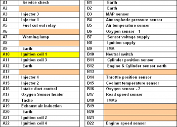
Connect the BNC moulded plug of the low-amp current clamp into Channel A of the scope. Check the manufacturer's pin data for the combined ignition and fuel injection Electronic Control Module (ECM) coil pack primary connection terminals. Place the current clamp around the correct wire as in Figure 1.
With the example waveform displayed on the screen you can now hit the space bar to start looking at live readings.
The current switches on as the dwell period starts and rises until the requisite 5 amps is achieved in the primary circuit, at which point the current is maintained until it is released at the moment of ignition. This moment of ignition is determined by the motorcycle's ECM.
The dwell angle expands as the engine revs are increased to maintain a constant coil saturation time, which explains why this system is called 'constant energy'. If the 'X' cursor is placed at the beginning of the dwell period and the 'O' cursor placed on the induced voltage line, the coil saturation time can be measured. This will remain exactly the same regardless of engine speed.
The purpose of the ignition amplifier is to switch the relatively high primary current of approximately 5 to 10 amps (depending upon the manufacture and system) to earth when the component receives a signal from the Electronic Control Module (ECM).
The output from the coil or coils is determined by the speed of the switching; the faster this occurs, the greater the voltage induced into the coil's primary winding.
The amplifier can best be described as a solid state relay, allowing a small current to switch a much higher current. Due to this high amperage, the component gets hot, and a liberal application of heat transfer grease should be applied to the mating surface to help dissipate the heat: without this precaution the component will overheat and fail. The earth connection is crucial to the correct operation of the amplifier.
The amplifier can also be referred to as a 'module' or an 'igniter' (Japanese term), and can be mounted either within the motorcycle's ECM or as an external and easily replaceable item.
Care should be taken when inspecting the ignition's primary current. The amperage is similar between different management systems but differs slightly. Any slow switching of the ignition module circuit will result in a lower than anticipated induced voltage and the earthing off point will be seen as a sloping line, rather than the perfectly vertical line. Should this point of the waveform be found to be different to the example waveform, the module/ECM should be tested or replaced.
Our test vehicle was a Honda motorbike. Below is the ECM multiplug pin data. Pin data will be manufacturer- and model-specific and this data is shown for illustration purposes only.


AT116-2
Disclaimer
This help topic is subject to changes without notification. The information within is carefully checked and considered to be correct. This information is an example of our investigations and findings and is not a definitive procedure.
Pico Technology accepts no responsibility for inaccuracies. Each vehicle may be different and require unique test
settings.
We know that our PicoScope users are clever and creative and we’d love to receive your ideas for improvement on this test. Click the Add comment button to leave your feedback.