PicoScope 7 Automotive
Available for Windows, Mac, and Linux, the next evolution of our diagnostic scope software is now available.
Automotive guided tests
Library of examples on how to perform tests when using PicoScope.

Training
Our collection of training videos, articles, guides and information on training courses.

Waveform library
The Waveform Library is a global database of waveforms uploaded by PicoScope users.

Case studies
Real-life case studies show how the professionals use PicoScope to diagnose vehicle faults.

A to Z of PicoScope
Detailed description of various PicoScope software and hardware features.

Videos
Training resources and demonstrations on PicoScope and the Automotive Diagnostics Kit.

Newsletter
Archive of our monthly Automotive Newsletters.

Documentation
Download manuals, brochures, posters, and training materials.

Reviews and awards
Accolades for the preferred diagnostic tool for service centers and vehicle manufacturers.

| Vehicle details: | Mercury Sable |
| Year: | 1991 |
| Symptom: | Engine stalling, P0326, Poor idle |
| Author: | Merrick Endres |
326 - EGR circuit voltage lower than expected
MAF sensor seemed to be in range based on DVM measurement, .6 to .9 V DC. However, unplugging
MAF sensor connector allowed a stable idle and the vehicle was drivable with the occasional stumble but
no stall at idle.
Engine generally idled okay until it was shifted out of Park, and then it started surging. Going back into
Park did not return to a better idle and continued to surge.
Time for the scope!
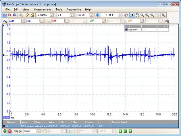
Here we have the MAF signal waveform, showing steady and heavy spikes. Average DC around .6 V
DC.
Here we have the MAF waveform after shifting out of Park- 1 V DC, saw tooth from MAF?

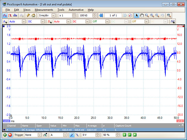
Here we see the alternator output and MAF sensor signal, where oscillations and switching spikes are
present. Could this be caused by the MAF or something else? Average DC is about .6 V DC
The oscillations would continue even after the engine had stalled. If the key was turned off and then
restarted, the oscillations were gone until triggered again by shifting. All accessible power and ground
circuits were checked and cleaned. I unplugged any accessible connectors; this improved the idle and
heavy spikes disappeared when the Axode2 connector to the transmission was disconnected. The
transmission pressure control solenoid (EPC) was included in that connector.
On cold start, MAF and EPC solenoid, idle okay, EPC switching spikes showing up on MAF signal.

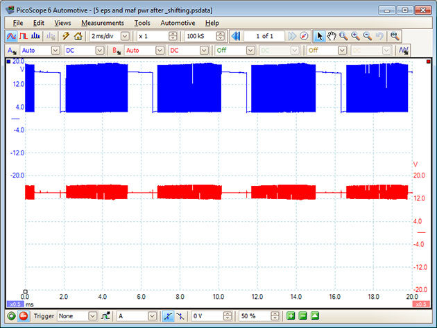
EPC and MAF power after shifting. Instability oscillations
I wondered about the EPC solenoid chattering or having a failed snubber, but the instability was too
uniform. Applying an external snubber diode only made the oscillations worse. It seems that the ECM is
the primary candidate. Opening up the ECM revealed 3 bad electrolytic capacitors.
After changing the 3 electrolytic capacitors, the car is working correctly and as expected.
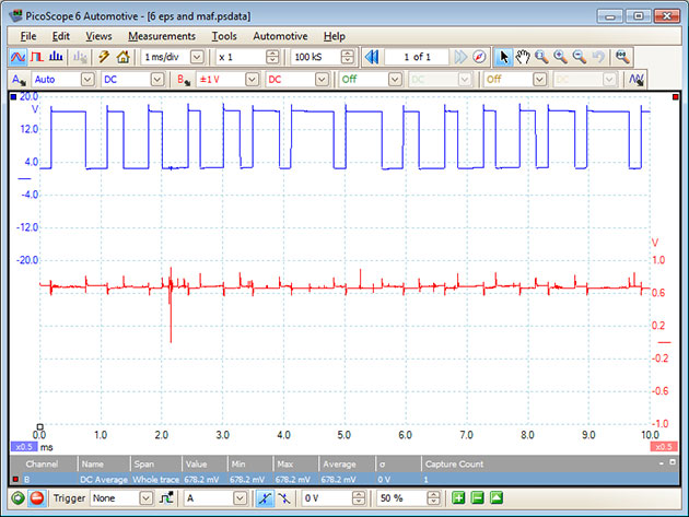
EPS and MAF signal, .68 V DC
.jpg)
One of the replaced ECM caps was part of the reference voltage supply circuit for the TPS and EGR
position sensor, and probably for the MAF sensor. That may be the cause of the 326 code.
Without the use of the PicoScope, the car may have ended up with a new MAF sensor, TPS, EVR, EGR
position sensor, EGR valve, etc.
Thomas
March 10 2013
Also, With Ford MAF’s remember to look at the the Baro reading. If it is normal, the MAF is likely OK. If it is showing 150 at sea level, or worse, it will change fuel trims and back off timing for altitude. This is an inferred reading on MAF Calculations.
rick
March 04 2013
I wonder if ac or garbage was visible on the 5volt reference line rather than a flat dc. If so perhaps jumping a filter cap on the line to prove a filtering problem.
Eddie
March 03 2013
Good skills by observing the irregular MAF patterns and then observing EPC after drawing a link to the fault occurring when shifting out of park. Unfortunately more modern PCMS are less able to be opened up for inspection or repair.
Merrick
March 02 2013
Thanks to all for your comments. And to Pico for their products and forums.
Some quick responses:
David Paterson- Interesting! You clearly have a pretty good understanding of the function of the electrolytic capacitor, which I suspect gives you a certain advantage of many of us! Would you like to share with us: a) How you spotted the 3 failed electrolytic capacitors; b) what caused their failure? This isn’t
>>Yes, I have a background in electronics. Electrolytics are common failure points in electronics. I think a typical failure mode in this application is temperature cycling which degrades the can’s seal, allowing the corrosive electrolyte to leak out. Corrosion of the cap’s leads or the circuit board are easy to spot.
http://en.wikipedia.org/wiki/Electrolytic_capacitor
James- In the photo of the ecm, can the failed parts be identified?
>>One cap is in this picture, the large blue can. Note the corrosion where the left lead is soldered to the board.
Will- What is a snubber?
>>Coils store energy during operation. When the circuit is opened a snubber provides a path for the energy to dissipate, protecting the switch or controlling circuit from a voltage spike (which can cause arcing at a switch).
http://en.wikipedia.org/wiki/Flyback_diode
—How do you know that a capacitor was bad?
>>All 3 showed signs of leakage, one measured low capacitance on a DVM. I changed all 3.
—You did not mention if you checked the MAF sensor for contamination.
>>An internet search suggested Ford MAF sensors are subject to contamination, resulting in degraded idle. “Goodâ€Â, I thought, “this will be an easy fix with the magic MAF sensor spray from the local parts storeâ€Â. The sensor wires didn’t look too bad, but I blasted them with the spray and hoped for the best. No change. Ford has the maintenance cycle built in- cooks the wires to burn off contamination.
James- Nice work, but did the Pico really expose the problems or was it the last resort to go to the computer.
Just a thought. still, nice call
>>Couple of things. At first I didn’t think I could get out the ECM without removing the AC dryer (and opening the system). So I kept looking for another cause. When it was down to something either inside the tranny or inside the ECM, I chose to make another attack on the ECM. It was my lucky day when I discovered I could pull the ECM out (behind the interior glove box) without making changes on the engine side of the firewall. I briefly considered (a few nanoseconds) troubleshooting the ECM with the caps in place, but I didn’t have a schematic nor any easy way to operate the ECM on the bench. The scope would have been necessary on that quest.
If I had known how to remove the ECM early on I would have solved the issue much earlier. Without the scope and not knowing how to extract the ECM, I might have submitted to changing out numerous other components, all to no avail. The scope was instrumental (duh) in getting the problem down to 2 possibilities.
James
March 01 2013
Nice work, but did the Pico really expose the problems or was it the last resort to go to the computer.
Just a thought. still, nice call
Will
February 28 2013
What is a snubber?
How do you know that a capacitor was bad?
You did not mention if you checked the MAF sensor
For contamination.
David Paterson
February 27 2013
Interesting! You clearly have a pretty good understanding of the function of the electrolytic capacitor, which I suspect gives you a certain advantage of many of us! Would you like to share with us: a) How you spotted the 3 failed electrolytic capacitors; b) what caused their failure? This isn’t
Mike Drapac
February 27 2013
Good work. Good tracking the problem down to the root cause. I see so many shops just hang parts until the problem goes away. That method might be profitable for the shop - however, it usually ends up with a dissatisfied customer. I have 3 pico scopes and use them all the time.
Good work. good story - well done.
Mike
Allan Pietersen
February 27 2013
This is real awesome. Any way never fear when PICO is near. Most definitely the best diagnostic tool.
James
February 27 2013
In the photo of the ecm, can the failed parts be identified?


