PicoScope 7 Automotive
Available for Windows, Mac, and Linux, the next evolution of our diagnostic scope software is now available.
Automotive guided tests
Library of examples on how to perform tests when using PicoScope.

Training
Our collection of training videos, articles, guides and information on training courses.

Waveform library
The Waveform Library is a global database of waveforms uploaded by PicoScope users.

Case studies
Real-life case studies show how the professionals use PicoScope to diagnose vehicle faults.

A to Z of PicoScope
Detailed description of various PicoScope software and hardware features.

Videos
Training resources and demonstrations on PicoScope and the Automotive Diagnostics Kit.

Newsletter
Archive of our monthly Automotive Newsletters.

Documentation
Download manuals, brochures, posters, and training materials.

Reviews and awards
Accolades for the preferred diagnostic tool for service centers and vehicle manufacturers.

| Vehicle details: | Audi A8 |
| Engine code: | BFM |
| Year: | 2003 |
| Symptom: | Cutting out, P0204, P0300, P0304, P1130, P1138 |
| Author: | Lee Hearnden & Mike Valentine |

Back-pinning Probe Set

20 A / 60 A DC (low amps) current clamp
*At Pico we are always looking to improve our products. The tools used in this case study may have been superseded and the products above are our latest versions used to diagnose the fault documented in this case study.
A 2003 Audi A8 was having a problem with rough running which in turn was causing the engine management light to illuminate.
The first stage of the investigation was to use a diagnostic tool and obtain any ‘DTC’ (Diagnostic Trouble Code) information and relevant data from the ECU. The scan tool showed the following codes stored in the DTC memory:
The first 3 codes concern general misfire and fuelling. These are probably due to the engine switching from Petrol to LPG and back.
As this was an LPG conversion, we didn’t trust the DTCs so we checked with PicoDiagnostics. This would help to identify the misfire, highlight any signs of rough running, and more importantly show whether the misfire was a mechanical error or related to a fuel or electronics issue. Figure 1 shows the results from PicoDiagnostics:

Figure 1
With the ‘Variation’ data enabled, PicoDiagnostics shows that each cylinder can produce a high amount of mechanical power (represented by the blue line). The above screen capture indicates that while cylinder H is mechanically OK, it does have an intermittent misfire. Further investigation is required into the surrounding components which supply the cylinder.
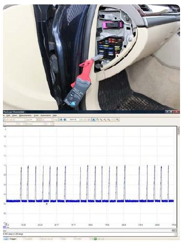
Figure 2
We assumed that the first 3 DTCs were due to the engine switching from Petrol to LPG and back. This is because these codes are general misfire and fuelling codes, which aren’t relevant to the fault under investigation. The PicoDiagnostics software backs up our theory.
From the ‘16588’ error code, there seems to be an issue with one of the injectors in the circuit on cylinder 4. At this point we cannot determine whether this is due to the LPG switching, so we carried out a quick test. Using the Fuse Adaptor and a current clamp we can see if all the injectors are drawing even current, if any were poor or even absent.
The screen capture to the right shows that there are only 7 current draws from the 8 injectors. This indicates that there is an issue with one of the injectors, or possibly the wiring harness.
One more check was carried out, which was to switch to the LPG system from the standard fuel system. As the LPG requires the ignition system, if all 8 cylinders fired correctly it would have proved that issue lay with the fuel injector.
The Audi A8 is designed with a sophisticated system that allows one or more cylinders to be deactivated in the event of a continuous misfire.
This is important to remember, as a simple test of resetting the ECU can be performed to show if the problem is continuous or intermittent (this is done by switching the ignition off and then restarting the engine). If the engine misfires intermittently, the ECU will register the misfires a given number of times before it automatically deactivates the fuel into this cylinder to prevent premature catalytic converter damage. This will then lead to a constant misfire.
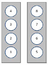
Figure 3 (front of vehicle)
We knew that we were currently firing on only 7 cylinders and so, before switching to LPG, we must switch off the ignition and restart the engine. Upon restarting the engine and switching to LPG, all 8 cylinders began to fire successfully. This confirmed what we had already suspected: that both mechanical power and spark were present.
The V8 configuration used by Audi (Figure 3) identifies the cylinders in the following order: left side first, numbered front to back, followed by the right side, also numbered front to back (as in the image to the right). With this information and the ‘16588’ error we now need to investigate cylinder 4 further with regards to the injector and circuit.
From here it was obvious that we would need to use the PicoScope Automotive software and begin running tests on the cylinder 4 injector. At this point it made sense to use cylinder 3 as a benchmark for comparison to determine if a difference could be seen, or more importantly if there was a fault with the injector or the wiring harness.
We then connected the PicoScope to the injectors on cylinder 3 and 4, measuring both voltage and current by connecting the channels as follows:

The following waveforms (Figure 5) were captured using the scope. The screen was split into two sections to allow a comparison of all measurements. The sections were set up as follows:
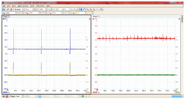
Figure 5
We can see that the cylinder 4 injector is not switching and therefore no current is being drawn. We can also see small voltage spikes, which indicate that there is possibly a high resistance in either the injector or the circuit, which is restricting the full voltage from reaching the injector solenoid.
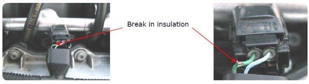
From this data we could identify that the problem was with cylinder 4’s injector, and that there was some kind of resistance preventing the full voltage from getting to the injector. We decided to strip back and remove the wiring protector to have a closer look at the wiring harness and take note of any breaks, short circuits or obvious problems.
We found slight breaks in the wiring insulation (possibly from previous testing) which might indicate that this was a previously investigated problem. However, these breaks were not sufficient to short to any earth wire or earth point and there were no other breaks within the wiring. From this we were able to determine that the problem was not occurring from these breaks.
At this point the multi-plug was connected back onto the injector and the engine was restarted for further testing. Upon restarting, we noted the misfire had disappeared. We retraced our actions to identify what could have affected the misfire problem. Our only thought was that we had removed the multi-plug and reconnected it with the harness removed. It was decided that a further test was required on the harness. The scope was reconnected to the ‘Fuse Adaptor’ with the current clamp, and a ‘wiggle test’ was performed on the harness. This returned no change in the results, so a slightly more aggressive ‘wiggle test’ was performed on the multi-plug, and at this point the cylinder began to randomly misfire. This can be seen on the waveform captured in Figure 7:
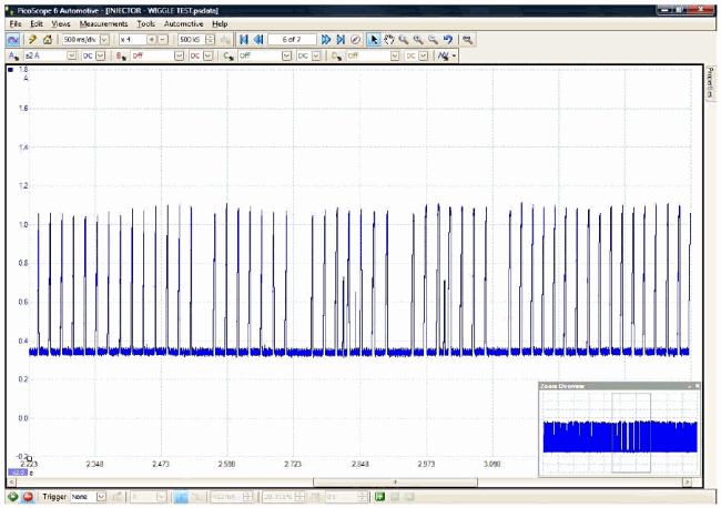
Figure 7

Figure 8
With the multi-plug removed (Figure 8), it could be seen that the terminals inside had pushed apart over time, and therefore were acting as a pivot when moving with engine vibration. This would cause an intermittent misfire as described in the original fault codes.
The multi-plug was stripped down and the terminal pins were replaced and refitted to the injector. The entire wiring harness protector was built up again and the engine no longer misfired.
The codes were cleared from the DTC memory and the vehicle was road tested, with no misfire present. To ensure the misfire had been resolved, the LPG was activated and deactivated while on the road test to ensure that the engine could cycle and run on the alternative fuel. No misfire occurred. After the road test, the scan tool was reconnected to check for pending and stored codes. The following codes were retrieved:
The 3 DTCs (see above) returned by the scan tool were due to the LPG running conditions when the fuels were switching over. This confirmed that there were no new DTCs returned that required further investigation.
Wayne Broady
October 19 2014
I know it has been some time since Case study entered but some comments below
the DTC codes still present indicate this still is a LPG fuelling issue - the mapping of the LPG injector is still affecting the Fuel trims and it shouldn’t - If Tuned and Mapped correctly these codes should not show
17546 P1138 17538 P1130 16684 P0300
khurram
July 27 2012
hi i have the same audi a8 4,2 liter. i hope you can help me out with a problem .. i am converting it to lpg but i cant get any signals to the lpg prins ecu .. i normally cut the minus wire to the injector and i did it here also but it will not give any signals only injector 2 is giving timing signal rest of the seven cyl is giving diverent values but they dont change .. can you please tell me which cable i have to cut in the injector plug .. thanks please reply me if you can on .(JavaScript must be enabled to view this email address)
RIMVYDAS
June 07 2012
Good job , and good way of thinking.
phil j
January 24 2011
i dont understand how the dtcs logged just because of the changeover from petrol to lpg only affected cylinders in bank 2 and why long term fuel trim is affected
Carl Grotti
October 24 2010
Hi Lee and Mike,
First of all, thanks for the case study.
I have a few questions myself if you don’t mind.
1) Was the PCM in catalytic convertor protection mode by disabling the #4 injector driver as seen in scope 2 view? It almost has to have been since your 4 volts wasn’t being pulled low. The first thing I would have done is go to the B+ side of the injector to make sure the supply is there. If it was still low (4V), then I’d work upstream from that test point.
2) Why doesn’t Alldata have any wiring diagrams for injection on your Audi A-8? Is this only in the VAG/VAS scan tool? I have very little experience with German built vehicles, but this seems wierd not having electrical wiring diagrams/schematics in a cataloged service information system.
3) Why is channel C and D in AC coupling mode? Are you trying to reduce noise from your low current probe with this method instead of deploying a filter?
Regards,
Carl
Tom Piippo
October 24 2010
I agree with Phil, you can assume nothing in diagnosis. I, too am curious in the 4 volts on the open injector ground circuit. Maybe a diagnostic bias? No note was made as to confirming power to the injector? And lastly, just to avoid confusion, (figure 4) isn’t cyl #1 on the front right, not the front left as stated?
All around a great article, I always learn a lot from these.
Phil Lynch
October 23 2010
I wondered why you would be looking for a short or open circiut when the voltage was not at zero When I Saw the voltage was at aprox 4 v. I would have been looking for an open circiut only.(would I have been wrong?.)Also I am wondering when you decided the first three codes were due to the fuel switching I would bet it was after the road test & after the problem was fixed, ( as you can not assume anything when diagnosing from codes.)
I Recently done a service on a vw polo and when removing the coils to inspect the plugs one of the coils left the shield on the plug exposing the coil wires. there appered to be no damage and could not get a replacement at that time of day. so I glued the steel shield back on to the unit. It was fine I road tested the car and code read it then gave it back to the customer. about a week later It came back in with a reported lack of power and stalling Intermitantly and light on dash, I code read and it came up with five or six codes Ranging fron fueling problems to Random misfires Even O2 sensor.
Knowing the resent history. I ignored all codes and replaces the coil I glued and hey presto it has been fine now for a couple of months. I Could have got bogged down with all them codes.
Usman Tariq
October 23 2010
I guess you have just mistyped something in the article. You have written :-
* Channel A (red trace) to the Injector Cylinder 3 Signal Wire Using the Acupuncture Probe
* Channel B (blue trace) to the Injector Cylinder 4 Signal Wire Using the Acupuncture Probe
* Channel C (green trace) to the Injector Cylinder 3 Signal Wire Using the Amps Clamp
* Channel D (yellow trace) to the Injector Cylinder 4 Signal Wire Using the Amps Clamp
But before Fig 6 it says the following which makes sense :-
* Left: Injector Cylinder 3 Voltage vs Current
* Right: Injector Cylinder 4 Voltage vs Current
Just the colors of Waveforms need to be swapped.
But anyways very informative and thanks for sharing
Steve Scott (Doc...)
October 11 2010
Nice piece of detective work, it raises a couple of questions for me though.
Was the LPG system factory or aftermarket?
What benefits do you perceive from using a dual scope view in this particular instance?
Was there a reason (apart from speed) for using auto ranging on the voltage scale?
Was this to allow you to pick up the small voltage spikes on Inj 4, were you expecting to see the spikes?
I assume you were using a 4000 series scope without attenuated leads given the 100v scale?
Good article, thanks for sharing.
Cheers
Doc…


