PicoScope 7 Automotive
Available for Windows, Mac, and Linux, the next evolution of our diagnostic scope software is now available.
Automotive guided tests
Library of examples on how to perform tests when using PicoScope.

Training
Our collection of training videos, articles, guides and information on training courses.

Waveform library
The Waveform Library is a global database of waveforms uploaded by PicoScope users.

Case studies
Real-life case studies show how the professionals use PicoScope to diagnose vehicle faults.

A to Z of PicoScope
Detailed description of various PicoScope software and hardware features.

Videos
Training resources and demonstrations on PicoScope and the Automotive Diagnostics Kit.

Newsletter
Archive of our monthly Automotive Newsletters.

Documentation
Download manuals, brochures, posters, and training materials.

Reviews and awards
Accolades for the preferred diagnostic tool for service centers and vehicle manufacturers.

| Vehicle details: | Ford Focus 1.6 (Duratec-16V) |
| Engine code: | SHDA |
| Year: | 2007 |
| Symptom: | Engine overheating, P0480 |
| Author: | Steve Smith |
The engine temperature gauge indicated hot with steam creeping from under the bonnet.
The customer informs that the issue has been present for 3 weeks and that a new cooling fan had been installed.
The engine temperature gauge moved towards hot when the vehicle was stationary for prolonged periods of time. If the vehicle was driven on open roads there were no overheating issue.
The customer interview revealed that the vehicle had begun to overheat approximately 3 weeks prior to my inspection and so it had not been driven since. During the 3-week period, it transpired that multiple second-hand engine cooling parts had been installed. These included a cooling fan assembly and a cooling fan control module accompanied with a coolant system flushing agent; all without rectification of the underlying fault. Given the multiple failed attempts to rectify the overheating issue, the customer had requested that the garage refit the original parts.
The basic inspection highlighted all the typical witness markings of previous intrusion about the cooling fan assembly, but nothing that suggested errors with the installation, the harness routing, the coolant level, a coolant leak or the cooling fan connections.
It was relatively easy to confirm the symptom in this scenario; I performed a scan of the PCM memory with the engine idling and the fault code: P0480 Fan 1 Control Circuit Permanent was revealed.
Live data inevitability confirmed that the coolant temperature was rising above 100°C with no intervention from the cooling fan. The cooling system pressure felt normal when squeezing the coolant hoses and monitoring activity within the expansion bottle. To take it to one more level, I used the scan tool to drive the cooling fan, confirming no response from the fan assembly.
By using the ALLDATA technical information system, no known cooling fan issues were listed with this model and so I obtained a wiring diagram in order to evaluate the operation of the cooling fan. An interesting point to note here was that I could not categorically confirm how the cooling fan was controlled other than a wiring diagram, therefore, I had to use a combination of discussions with colleagues, my training, and prior experience to confirm this.
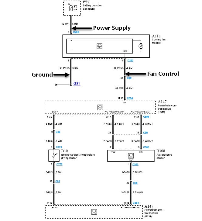
The following wiring diagram was provided by ALLDATA.
When looking at the wiring diagram above, we can see how the cooling fan module is supplied with power via Fuse 1, ground at point G37 and a single fan control wire from the PCM. From my perspective, I had to determine if the cooling fan could at least function, so I used the appropriate breakout lead from our breakout lead set. A simple connection across the vehicle battery saw the cooling fan burst into life. Now, I had an opportunity to monitor the current flow through the cooling fan while it was running at maximum speed.
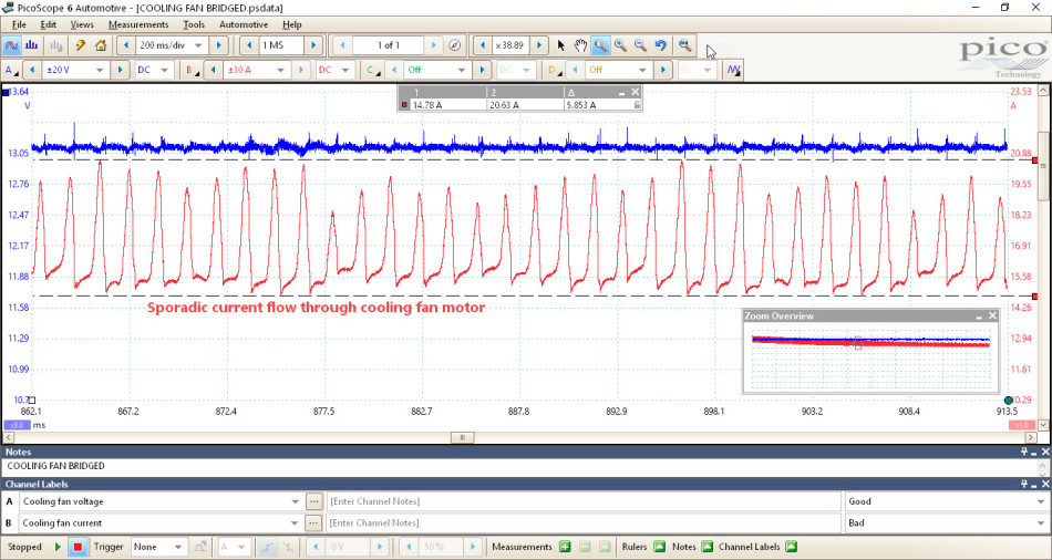
While I could confirm the cooling fan operation, the sporadic current flow highlighted an underlying issue with the fan’s motor brush assembly. The following case studies also demonstrate how much detail can be revealed using a current clamp to evaluate the serviceability of motor assemblies:
At this stage, I had to inform the customer of my findings and the potential for future failure of both the fan motor and cooling fan module responsible for delivering this demanding current. This way you can protect yourself from repeat visits that could be mistaken for incorrect diagnosis as the symptom of the cooling fan motor failure would be identical to the customer’s complaint above. By documenting each step of the diagnosis (as with the waveform above) you obtain a time-stamped conclusive evidence of measurements taken and recommendations made.
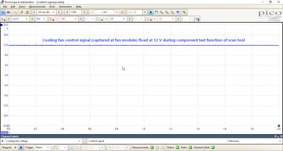
Now, I moved onto the three wires connected to the cooling fan module. Power and ground were confirmed as correct, while a stable 12 V was measured on the blue fan control/signal wire. Based on discussions with colleagues, I concluded that the fan control wire is supplied with 12 V from the fan control module, which is pulled to ground via the PCM at a specific frequency in order to control the fan operation and speed. For the fan control signal to become active, the engine temperature is required to increase to a predetermined level (approximately 100°C), or the fan has to be driven by using the component test function in the scan tool. It became apparent that no control signal was present on the fan control wire, which remained fixed at 12 V regardless of temperature or scan tool intervention.
I had a number of points to consider:
Based on the initial diagnosis and the summary above, I had to qualify the integrity of the fan control wire between the fan control module and the PCM. If this signal wire was intact, I would have to make a call as to which component to replace. Remember that the fan control module had been substituted previously with a second-hand unit, which is no way to form a conclusive diagnosis.
In order to confirm that the PCM was attempting to communicate with the fan control module via the blue signal wire, I disconnected the fan module and, once again used the scan tool to drive the cooling fan while monitoring the signal wire (at the fan module) with PicoScope.
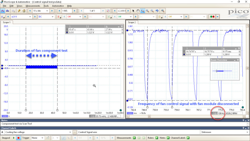
The results were interesting given that the fan control module was disconnected and so there was no signal voltage (12 V) for the PCM to pull to ground. However, the disconnected fan control module resulted in a bias voltage of approximately 1.3 V on the signal wire which must originate at the PCM. More importantly, during the component test, the bias voltage is pulled to ground at a frequency of approximately 110 Hz. This was proof enough to me that the PCM was at least attempting to control the cooling fan, confirming the integrity of the PCM and control wire – or did it?
In the back of my mind, I have this niggle that removing components from a circuit in order to measure voltage is not a true representation of how the circuit is designed to function i.e. we have removed the load.
How could I prove the integrity of the fan control wire with 100% certainty?
A load test, where I put load on the cable by using a power supply and a bulb was the perfect solution to determine if the control wire carried current. In this scenario, to get to either end of the fan control wire, I had to remove the PCM security bracket, which can only be described as a mission itself.
I chose to go for continuity testing, by baring the control signal wire as close to the PCM connector as possible. The continuity test revealed a fluctuating value when I wiggle-tested the harness of the cooling fan module.
By following the wiring harness across the slam panel and under the LH headlight, I found the familiar signs of corrosion or water ingress into the copper cables.
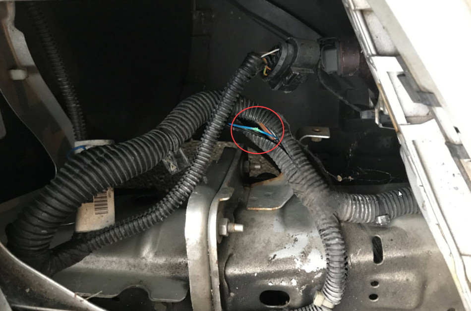
Closer inspection confirmed that the fan control wire was almost open circuit, but had a sufficient amount of copper strands to deliver the bias voltage I saw in the previous waveform. This is why the continuity method of testing is flawed. The multi-meter leads you to believe that the circuit is complete, which is true, but only via single strands of wire that will not carry load.
The harness was promptly repaired and I ran the cooling fan by using the scan tool component test function.
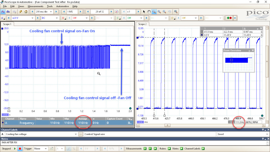
In figure 6 you can see how the fan control wire is pulled from 12 V to ground at a frequency of approximately 110 Hz. This is identical to the frequency measured with the bias voltage while the fault was apparent.
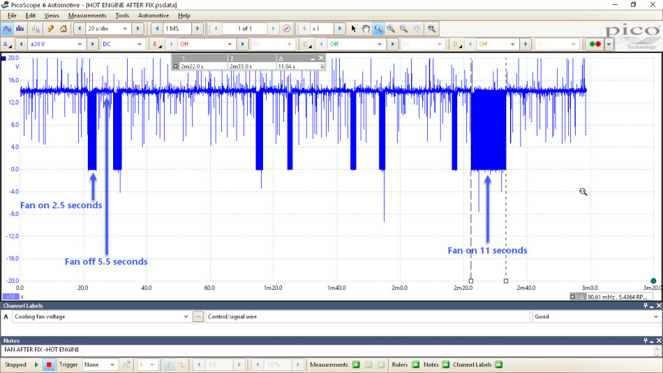
The final confirmation was that the PCM could control the cooling fan (without instruction from the scan tool) but required the engine to be run to approximately 100°C. This revealed an interesting strategy from the PCM. The cooling fan runs in a pulse fashion for a minimal amount of time sufficient to lower the coolant temperature. This prevents over-cooling, reduces emissions and engine load (via the alternator) while improving the fuel consumption. Should the engine coolant temperature continue to rise, the PCM has infinite control. You can see this as the cooling fan ran for 11 seconds towards the end of the waveform below.
On this occasion, no replacement parts were required, but I recommended that the customer replaced the cooling fan motor assembly.
Steve
August 23 2020
Does this meen the pcm can control the fan speeds or just turn the fan on and off?
Mike
January 09 2018
Hi Robert,
On this particular vehicle we were able to disconnect the fan from the module via a multi-plug. Using jumper leads to connect to the vehicle’s battery we are able to supply 12 V to the fan in order to power it, and therefore monitor the current.
Mike
January 09 2018
Hi Sandy - On this occasion the bulb was used to prove the circuit could carry load, no current measurement was taken.
sandy anderson
August 01 2017
Excellent article, explained very well the diagnostic steps, can I ask what was the current draw of test bulb/light you used (200-300 milliamps)? Cheers sandy
Robert Lesaca
July 31 2017
In the absence of bi-directional control feature of a scanner, how do you activate the fan after disconnecting the fan module? Also, how did you connect across the battery to initially run the fan? I need visualization to fully understand the steps you did. Thank you.