PicoScope 7 Automotive
Available for Windows, Mac, and Linux, the next evolution of our diagnostic scope software is now available.
Automotive guided tests
Library of examples on how to perform tests when using PicoScope.

Training
Our collection of training videos, articles, guides and information on training courses.

Waveform library
The Waveform Library is a global database of waveforms uploaded by PicoScope users.

Case studies
Real-life case studies show how the professionals use PicoScope to diagnose vehicle faults.

A to Z of PicoScope
Detailed description of various PicoScope software and hardware features.

Videos
Training resources and demonstrations on PicoScope and the Automotive Diagnostics Kit.

Newsletter
Archive of our monthly Automotive Newsletters.

Documentation
Download manuals, brochures, posters, and training materials.

Reviews and awards
Accolades for the preferred diagnostic tool for service centers and vehicle manufacturers.

| Vehicle details: | Toyota Auris |
| Symptom: | Hybrid Warning Light, P0A82 |
| Author: | Steve Smith |
It goes without saying that hybrids and electric vehicles (EVs) should be treated with caution when it comes to service, repair and of course, diagnostics. This comes as no surprise, and while the same applies to any vehicle, with EVs and hybrids there are added dangers. We should not be fearful of such technology, though, once we understand the safety procedures involved and the operation of the system we wish to diagnose.
Here is one such case where a Toyota Auris hybrid arrived with the Hybrid Warning Light illuminated. The vehicle had been converted for covert surveillance with sensitive recording devices spread throughout the cabin.
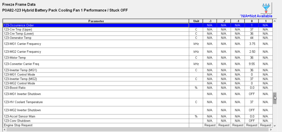
Trying not to be phased by what lies beneath and keeping an eye on the ball, we extracted the fault code P0A82-123 from the Hybrid Control Unit (HCU). Hybrid codes include what are known as INF (information) codes and, in this case, we had P0A82 as our DTC and 123 as our INF code.
The INF code provides a thorough and specific overview of hybrid component operation before, during and after the point of DTC detection, so assists technicians with historical facts to support a conclusive diagnosis.
Access to an OEM scan tool allowed interpretation of the INF code to reveal “Occurrence order 1”. This indicated P0A82 was the initial code that illuminated the hybrid warning light and provided immense value where multiple fault codes are stored.
The DTC P0A82 referred to “Hybrid Battery Cooling Fan Performance error”.
A description of the system and fault code indicated a problem with the cooling fan control circuit responsible for cooling the high voltage (HV) battery. Understanding the operation of the system is essential when diagnosing recorded faults; after all, how can we diagnose components if we don't know how they function?
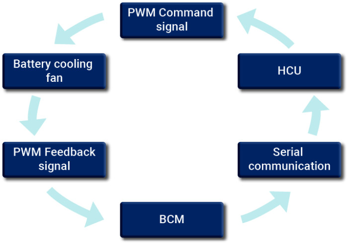
The speed of the battery cooling fan is controlled in a loop fashion by the HCU. A command signal from the HCU is delivered to the cooling fan to increase or decrease fan speed, depending on battery temperature. A feedback signal from the cooling fan is sent to the Battery Control Module (BCM), where this value is converted into serial data and returned to the HCU, completing the loop.
An initial inspection revealed the cooling fan to be running continuously at high speed, which had been difficult to detect amongst the surveillance equipment.
In order to access all the relevant components for circuit evaluation, the hybrid system is required to be shutdown using the following procedure:
Ignition off and key secured at least 2 meters away from the vehicle.
The HV system is now shut down and it is safe to continue with the diagnosis.
Access to the BCM is via the HV battery cover and so mildly intrusive into the heart of the HV system. At this point, there was no need to feel uncomfortable as the HV system was shut down as above.
Testing the cooling fan circuit required the 12 V battery to be reconnected and the ignition switched on, with the hybrid system still isolated. This is normal procedure and generated additional DTCs (which were erased on completion of the repair).
Note: Switching the ignition on with the HV Service Plug removed does not activate the HV system.
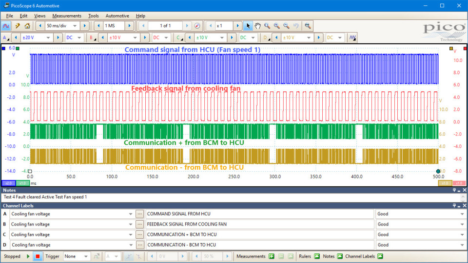
With the ignition on, PicoScope was connected to the command and feedback signals (CH A and B) along with the serial communication signal (CH C and D) within the cooling fan circuit.
Immediately we could see the command signal fixed at 0 V instead of the required PWM signal.

A continuity test of the command signal wire revealed a short circuit to chassis ground at one of the surveillance camera mounting bolts, resulting in a default max. fan speed to ensure sufficient HV battery cooling.
With the short circuit repaired, full closed loop control of the battery cooling fan was restored and confirmed using the component test function of the scan tool.
To conclude:
We shouldn’t be alarmed by HV systems; there are dangers with all vehicles regardless of their power source. Safety is always paramount, so ensure your safety training is up to date, follow repair manual procedures, understand the operation of the system under test and document your results during diagnosis.
Alich Karsten
January 25 2019
Danke für die Tolle und detaillierte Informationen so konnte ich den Fehler in der Anlage von meinem Bruders Yaris beseitigen was Toyota ja nicht geschafft hat, schön anderen zu helfen die hatten zwar alles da konnten aber den Fehlerdiagnostizieren, jetzt ist wieder alles gut dank Pico ...
Malcolm Lambert
October 01 2017
Very interesting reading and quite timely as well. I have just been working on a 2006 Lexus RX400h and was looking at that loop circuit from HV ECU to cooling fan to Battery smart ECU and back to HV ECU. It was good to see the result of the command signal grounded in this case.
In my case i had a poor Serial Comm signal back to HV ECM from Battery smart ECU. This would throw a fault code when the cooling fans came on. The pico scope showed a good signal when the fans were off and poor when they were turned on. The Cooling Fans were the cause of the fault.
Mahinda Ekanayake
October 01 2017
BRILLIANT INFORMATION THANKS PICO TECHNOLOGY.
Mark Stammers
September 30 2017
Really nice case study Steve, very informative and illustrates how these vehicles are not to be afraid of.
Jorge Vega
September 29 2017
Very interesting case, very well presented.
Also, I think a picture of the place where the signal was taken with the probes, would be very good to have a better picture of the procedure.
Bashar Alqasim
September 20 2017
Very informative and a brilliant presentation. only if the ; no AC or DC voltage at the HV invertor was shown. Also the article didn’t mentioned the required specifications of the HV probe that can be connected to the PicoScope. While I’m putting this enquiry, it is important to mention that I’m trained (to Level 3) and qualified to work on the High Voltage systems.