PicoScope 7 Automotive
Available for Windows, Mac, and Linux, the next evolution of our diagnostic scope software is now available.
Automotive guided tests
Library of examples on how to perform tests when using PicoScope.

Training
Our collection of training videos, articles, guides and information on training courses.

Waveform library
The Waveform Library is a global database of waveforms uploaded by PicoScope users.

Case studies
Real-life case studies show how the professionals use PicoScope to diagnose vehicle faults.

A to Z of PicoScope
Detailed description of various PicoScope software and hardware features.

Videos
Training resources and demonstrations on PicoScope and the Automotive Diagnostics Kit.

Newsletter
Archive of our monthly Automotive Newsletters.

Documentation
Download manuals, brochures, posters, and training materials.

Reviews and awards
Accolades for the preferred diagnostic tool for service centers and vehicle manufacturers.

| Vehicle details: | Hitachi Zaxis 135 |
| Symptom: | Poor acceleration |
| Author: | Ben Martins |
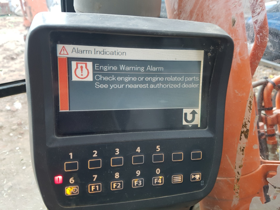
Once again, I find myself standing in a muddy building site. This time looking at a machine with a number of warning faults. The operator could no longer increase the engines RPM in order to move the machine off-site. As I’ve mentioned in previous studies, working with plant machinery is challenging, with a lack of information and an infinite amount of configurations in the circuitry between the engine and the hydraulics. Invariably, you have no idea what it is you will be working with. With the market for generic scan tools in this sector verging on zero, facing a number of warning lights on the display could have you reaching for the phone to call out the manufacturer. However, armed with a scope, we could at least build a picture of what is going on before making such a call.

Some plant manufacturers actually do try to help you with on-board diagnosis where, providing you press the right buttons, it gives you a view behind the scenes. This was indeed the case with this machine and, fortunately, we found the service menu from the operator’s manual and gained further information from it. There was a section in this menu that allowed us to view what appeared to be serial data. This was great as, unless we needed programming capability, it meant we could further our diagnosis without the needing dealer tools.
We had a fault with uncontrollable engine speed, so it would make sense to focus on both the target and actual engine speed. We were surprised to see that the figures were blank for both! Not only this, but there was some information, such as oil temperature and coolant temperature, meaning the display was able to see some engine related components. Another nice part of this service screen is the option to see pump pressure, as they had placed a sensor in the hydraulic system. Again though, this was also blank.
We know the engine would start and run so in theory, we should have a good crankshaft signal as this is a common rail diesel engine. Never one to assume, though, I figured it would be worthwhile ensuring that this was the case as well as having the opportunity to grab a cam/crank reference for future work. Getting to components on plant machinery is not the most pleasant of experiences. Most are buried behind protection plates designed to stop debris getting into places it shouldn’t. What this also means is anything that did get in can’t get out, leaving you with an oily, dusty environment that is just ready to coat you and anything else that comes near it. We confirmed the signal wire and managed to fit the universal breakout leads and grab our capture.


Crankshaft sensor
Camshaft sensor
Injector 1 current
You’ll see I’ve also included camshaft and injector 1 into the capture, purely for future use, as they were easily accessible from the top of the engine. It makes sense if you are looking to get the crankshaft sensor signal to also add the cam and a possible sync signal. Providing there is no fault with the running of the engine you will have a known good reference for future cases. Uploading to the waveform library also stores your waveforms on Pico’s servers which means that you will never lose them. For further information on the waveform library, please visit our website - https://www.picoauto.com/library/waveform-library or our YouTube video - https://youtu.be/8ePHLmRI5YY
Confident that the engine was providing the right signals, we turned our attention to the communication side of the machine. Somehow, the engine ECU will relay the engine speed to the information display in the cab, which we know is reporting nothing for target speed and actual speed. How does this information get to the display? The answer is CAN and the need for a wiring diagram was now a must. For a number of these machines, you can find a manual online. When faced with these types of problems they are vitally important.

Exactly as I thought. Sometimes I’ve found that redrawing the circuit you are only interested in, can help to focus on what it is you are trying to measure. We were only interested in the CAN network and the engine speed dial used to increase and decrease RPM.

Above is the re-drawn wiring diagram taken from the original wiring diagram with only the parts we are currently interested in. As you can see, the request for engine speed change via the speed control dial talks to both the Information display (INF) and the Machine Control ECU (MCU). However, the message for an engine RPM increase goes via CAN, most probably from the MCU to the ECM, with further information and data sent to the INF display. This would explain why some engine data was still present as it was being shared over the network.
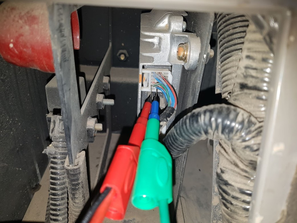
Having a theory and proving it are two very different things. Knowing that the signals for engine speed are sent over the CAN network, it might be good to take a look at the network. I used the PicoScope to observe communication between the ECUs. Noone likes condemning an ECU, so the more evidence we could get the better. Maybe the network could show us something different. Gaining access to the CAN wires is fairly straight forward on most vehicles with an OBD port but not so easy on plant equipment. We managed to find the correct wires and observed the network. What we saw was very interesting.
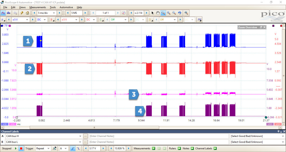
CAN High
CAN Low
A+B Math Channel
A-B Math Channel
By using the math channels to help with CAN faults, we can see something odd happening in the A+B channel on certain packets of data. Looking at the data on the right-hand side of the buffer, there are three packets followed by another four. The first three have a slight disturbance when data is transmitting, but they still sit within the 5 V we would expect to see. The last four, however, all seem to be pulled higher. By zooming in and comparing the two, it revealed even more information.
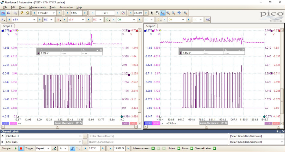
In Scope view 1, we have one of the packets from the first three, and in Scope view 2, we have a packet from the final group of packets. We can see the difference. The data in scope 2 has some distortion when adding the channels together and looks very disorderly compared to the data in scope 1. With A-B we can still see that, despite some irregularities with the voltage, the packet is still clearly there and it will decode perfectly. What you may notice here is the difference in voltages when looking at A-B. This may not be anything at the moment, and without a known good reference we are a little in the dark, but it could be down to the electrical signature of an ECU. More about this can be found in this forum topic: https://www.picoauto.com/support/topic21680.html#p98339
Not knowing if this is correct or not, the decision was made to open up the control handle to check the speed control dial. A simple 3-wire device with a 5 V supply, ground and signal output. It made sense that if this was no longer outputting a signal to the MCU there would be no request for a change in engine speed.

A quick check with the ignition on should supply the dial with 5 V from the MCU. We had nothing. It would have been nice to carry out a resistance test, and I suppose we I could have unsoldered the terminals, but as usual, time was ticking. This may have been another test to do following the results of the next test.
Seeing that this 5 V feed was missing and referring back to the wiring diagram, it wasn’t just the speed control dial that used the 5 V. Following the wiring, the feed also supplied the hydraulic pump pressure sensor which was blank when we looked on the instrument panel. Could this be the issue? Was the lack of 5 V not allowing us to control the RPM?
The next step was to locate the MCU ECU, which after a lot of hunting we found it behind a panel above the batteries, bolted to the engine ECU.

We ensured that the power and ground supply to the MCU was ok, and could confirm that there was no 5 V present for the engine speed control dial. We had reached the moment we all dread and a new MCU had to be ordered.
Fitting the new MCU was a simple plug and play, and did indeed cure the fault with the machine. The 5 V reference we were originally missing returned and the trouble codes we had on the information display were no longer present. This also meant the machines RPM could be altered using the Speed Dial on the panel.
But what about the network capture we made. We know it is a known good machine now, so grabbing the known good data is always going to help for future puzzles.

Here we have the capture from the same location as before, but with a little more time on the screen. I’ve kept the sample rate fairly high to help with the definition of the packets. Immediately CAN H + CAN L is looking very similar with the packets moving away from the 5 V line we would normally look for. However, we can still see that when we apply A-B we have data that is decoded correctly. What I noticed, though, is that there is a lot more traffic on the network now. If we split the screen in half we have a total time of 50 ms, the same as the original capture and we can clearly see that there is more data present.
As mentioned earlier, I referred to a post on the forum regarding the electrical signature of an ECU. I quote: “The dominant voltages (CAN Hi 3.5 V & CAN Lo 1.5 V) present on the BUS during the transmission of the message/payload will be unique to the CAN Controller transmitting the message due to manufacturer’s tolerances within the ECU, connectivity, varying components and its physical location on the BUS.” This unique signature for an ECU is going to be heightened even more with plant machinery, as there are varying different manufacturers involved with the creation of a machine. The engine ECU could be from Mercedes, Isuzu or Doosan. The information screen could be from any number of manufacturer and the machine ECU is from the people putting it all together. With this amount of variables, we have to allow for a greater level of tolerance for communication networks and accept the differences in CAN voltages. This is where a known good waveform can really stop you heading down the wrong path. It’s advisable that when confirming your ‘fix’ that you get that saved for future reference, or save and share to the waveform library. This way all your known good captures are stored safely and can be called upon whether you need them.
We know that replacing the MCU ECU has fixed the fault, but what actually happened to cause the fault in the first place? Given the opportunity to take to the ECU back to Pico and inspect further was an opportunity I could not miss.

During the initial inspection, with everything covered in dust, nothing was completely burnt out. We did notice, however, some corrosion to a component on the board. When we put this under a microscope more was revealed.

It’s difficult to say whether the MCU failure was down to this, but it certainly wasn’t helping anything. Given the hostile environment these machines are working in, it makes you wonder why the ECUs aren’t better protected from the elements.
Tim Harlow
February 07 2022
That is a very interesting report clearly written and partly understood
Hamza
December 02 2021
I have hitachi excavator zaxis 330 with the same problem I replaced mcu but still no changes
Hamza
November 13 2021
I have hitachi excavator zaxis 330 with the same error the 5v is missing from the dial switch i replaced the mcu but no changes i installed mu mcu in another excavator it works fine any idea please


