PicoScope 7 Automotive
Available for Windows, Mac, and Linux, the next evolution of our diagnostic scope software is now available.
Automotive guided tests
Library of examples on how to perform tests when using PicoScope.

Training
Our collection of training videos, articles, guides and information on training courses.

Waveform library
The Waveform Library is a global database of waveforms uploaded by PicoScope users.

Case studies
Real-life case studies show how the professionals use PicoScope to diagnose vehicle faults.

A to Z of PicoScope
Detailed description of various PicoScope software and hardware features.

Videos
Training resources and demonstrations on PicoScope and the Automotive Diagnostics Kit.

Newsletter
Archive of our monthly Automotive Newsletters.

Documentation
Download manuals, brochures, posters, and training materials.

Reviews and awards
Accolades for the preferred diagnostic tool for service centers and vehicle manufacturers.

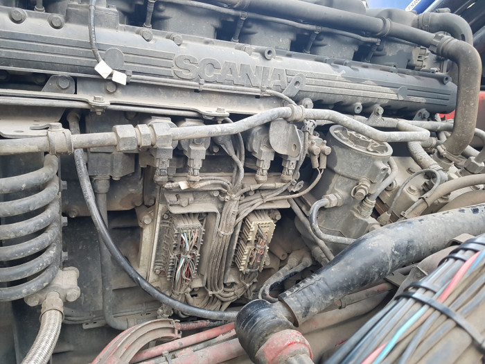
| Vehicle details: | Scania R480 |
| Engine code: | DC13 |
| Year: | 2008 |
| Symptom: | Engine misfire |
| Author: | Ben Martins |
I was recently asked to take a look at a 12.3 litre HGV. Trying not to be daunted by the fact that this thing was huge and that the last time I worked on an HGV was about 8 years ago, the one thing that kept creeping back into my mind was what they told me when I started in the trade: The fundamentals are the same in any ICE (internal combustion engine). It can be anything from a ride-on lawnmower to a combine harvester. How things are measured only depends on the manufacturer and the system used.
As usual, getting all the information is key to any diagnosis, and most importantly, understanding how the system works. This particular engine was jointly developed by Scania and Cummins, and I have to say there really isn’t an awful lot of technical information out there. I was lucky enough to have some assistance on the day, and they had access to this information.
The customer interview is always important at this stage in the diagnostic process. The operators of these vehicles spend a lot of time with the machine and can subsequently tell if something is wrong just from the way it sounds. With this particular lorry, a slight misfire had started at idle, which became progressively worse over time. There were no warning lights on the dashboard, but a strong fuel smell along with smoke and a heavy diesel knock when it was started up from cold; all the characteristics of over-fuelling. This improved as the engine warmed up, but with the engine at idle and during use of the crane for long periods of time, the smoke and the misfire returned. Again, as I mentioned earlier, it is important to gain a better understanding of how the system works before you can make an action plan.
A few things to understand about this engine and the way it injects fuel is that it is very different to anything I’m used to seeing on automotive vehicles. The engine itself has individual cylinder heads for each of the 6 bores and the injectors are mechanically operated by a pushrod. You might think that this would mean any misfire or fuelling issue could only be down to an injector, as there wouldn’t be anything else there to control it. That was my thinking prior to looking further into how the system works. The system has the ability to alter how much fuel is injected and how long it will open an injector for, by using four solenoids that are attached to a fuel gallery that links the front bank of three injectors and the rear bank of three injectors. Instead of using electrically controlled injectors, this engine uses diesel pressure to act hydraulically on the injector to determine how much fuel to inject when the mechanical rocker depresses the upper plunger. I guess in some ways this is similar to VW’s PD engine but without the electronic control.
The set of six injectors are linked in threes, three at the front and three at the back of the engine. Now it isn’t as straightforward as I first thought.
It would be really easy to go headstrong into looking at all this new information and checking the controlling solenoids, measuring fuel pressure, or looking for a leak of pressure. However, this is when you should come back to your diagnostic process. Following your own step-by-step procedure will give you a moment to find your next step. In this particular case, it was to check the DTCs (diagnostic trouble codes). Despite there being no warning lights on the dashboard, there may well be fault codes stored that will help steer us in the right direction. These can often be historic or pending fault codes if there was an intermittent fault. A quick scan of the ECM (engine control module) found a crankshaft sensor rotation fault. Again referring back to the technical information and the EWD (electrical wiring diagram), there were two inductive crankshaft sensors positioned near the flywheel.

Now, I have scoured a lot of websites to try and find out why there are two sensors and I am still none the wiser! The only thing I can think of is that these sensors help determine a reference for the front and rear bank of injectors for a more precise injection, but in all honesty, I really don’t know! There is no camshaft sensor as it is a fixed gear so any timing is done by fuel and, apart from a rail pressure sensor, there isn’t really anything else to monitor injection precisely.
I decided that if there was an issue with a crankshaft sensor then I really needed to check this out first. If there was a fault code then something must have happened for it to be triggered, so we continued our investigation at this point. Sometimes just confirming what it isn’t is just as important as what it actually is. One thing the scan tool couldn’t determine for us was which sensor we needed to look at, so we went back to the wiring diagram to find the connectors. Again, something I’m not used to seeing is the sensor plugs and other plugs individually connected directly to the ECM
With no technical information, it would have a taken a lot longer to determine which plugs were the crankshaft sensors, so the EWD saved us a lot of time here. As this would only take two channels, I thought I may as well utilize the fact that I had two spares and decided to also look at current draw from the timing solenoids. The Pico breakout leads made it possible for me to keep the connection and not disturb the wiring loom. By capturing the timing solenoids, I had a rough trigger point for each cylinder. It could also highlight a potential sticking solenoid which could affect our engine’s performance.

With everything connected, it was time to start the engine and see what was going on.

Straight away you can see that there is something not right with the waveform on Channel A when comparing it to the waveform on Channel B. Channel B has what we would think of as a good waveform pattern, with the typical AC signal and the gap for crankshaft position reference. This is not the case for Channel A which looks as if it has no gap but is seeing two smaller pickup points and the odd reverse effect on the lower half of the signal. Unfortunately, with no WiFi available, the waveform library was not available to me to check for a reference. But I was not to be defeated. There were at least two other R480s on site, meaning I could get my hands on a known good capture.

As you can see, channel A is massively different compared to our faulty vehicle. This was enough evidence to give us a reason to take out the sensor and inspect it. Also, this particular vehicle had an inspection plate situated between the crankshaft sensors’ locations and removing this plate gave us a window to a lot more information than we thought.

We saw the drilled holes used as teeth for the flywheel and the “missing teeth”, which in this case was a non-drilled section of the flywheel. Not only could we see that, but we also saw damage to the ring gear. This could be down to a number of reasons but we were now working against time. The transport companies just want their trucks back on the road as quickly as possible and every minute it’s not on the road it is costing them money. It would have been nice to explore this further and maybe find the missing pieces, but it did begin to paint a picture as to why we have a peculiar crankshaft sensor pattern. All this extra metal floating around the bell housing was bound to cause some issues and once we had removed the crankshaft sensor with the bad waveform capture we could see why it was so bad.

It is quite clear that this sensor was not in a good way. Probably from pieces of the broken ring gear, but that would be difficult to prove. There was, however, enough proof that the sensor needed to be replaced and that before we went any further we needed to fit a new one. Fortunately, there was a local motor factor that had the part and could deliver it to us within the hour. We had it fitted and were ready for a re-test.

As you can see the trace is a lot cleaner now we have the new sensor in place and what was also noticeable was that the misfire was nowhere near as bad. The smoke and the smell of unburnt fuel were also not present anymore, nor was the sound of diesel knock. There was still a slight judder in the mid RPM range but the technician I was working with said he wouldn’t be replacing any more parts until he had carried out a top end adjustment. This is a setup for the injectors which are something that is very important to these engines and he believed a lot of the leftover ‘judder’ could be eradicated by carrying out this procedure. Clearing the codes and carrying out a re-check saw the crankshaft code delete and not reappearing after a couple of cycles and a drive around the block.
I think the important thing to take from this study is that we do keep going on about technical information but it is becoming more and more vital as technology improves and moves forward at an increasingly fast pace. As this continues we should also be prepared to advance ourselves, and training is always going to be extremely important. We’re never too old to learn new things and I find myself constantly learning something new every day.
Two crankshaft sensors! Why? If anyone knows please leave a comment below, as I would like to know.
Terence
July 22 2020
Thank u for the info,its so relevant.l am having same problems wt my r420.its smoking&its; sounds like it has a diesel knock.after driving it for approximately 100kms,its writes the following on the dash-“engine malfunctioning,gearbox malfunctioning&alternator; not charging then the engine dies.You have to wait for some minutes before it can start again.can someone enlight me please.thank you.
Roberts
December 21 2017
Two speed sensors - because EMS measure gradual speed increase or decrease between these two sensors to adjust fuel quantity and correct time for each stroke - engine balance.
Tom
December 20 2017
I believe two crank sensors are there for redundancy purpose. Lets face it no crank singnal no running. Last thing you want is 40 ton wagon blocking the road over a cheapish part. Reliability in hgv is paramount for good sales. Them scanias are loved by many for a very good reason
Tom Harvey
December 20 2017
I can only imagine the two sensors might give a more accurate time reference to determine cranking speed or higher rpm signals as both impulses would be closer together allowing an input to the injection algorithms.
Luis Llumiquinga
December 20 2017
Thank you very much, I have learnead somethin more abouth this theme
Liviu
December 20 2017
In marine applications, one crankshaft sensor is used for control and the other one for protection, overspeed shutdown. And separate controllers, in that big ecu, might be two independent controllers. Just a guess, nice job. done there.


