PicoScope 7 Automotive
Available for Windows, Mac, and Linux, the next evolution of our diagnostic scope software is now available.
Automotive guided tests
Library of examples on how to perform tests when using PicoScope.

Training
Our collection of training videos, articles, guides and information on training courses.

Waveform library
The Waveform Library is a global database of waveforms uploaded by PicoScope users.

Case studies
Real-life case studies show how the professionals use PicoScope to diagnose vehicle faults.

A to Z of PicoScope
Detailed description of various PicoScope software and hardware features.

Videos
Training resources and demonstrations on PicoScope and the Automotive Diagnostics Kit.

Newsletter
Archive of our monthly Automotive Newsletters.

Documentation
Download manuals, brochures, posters, and training materials.

Reviews and awards
Accolades for the preferred diagnostic tool for service centers and vehicle manufacturers.

| Vehicle details: | Subaru Legacy SE |
| Engine code: | EJ25/056542 |
| Year: | 2005 |
| Symptom: | ABS fault, Engine misfire (intermittent) |
| Author: | Steve Smith |
There is noise/vibration from under the bonnet when driving at low speed over speed humps, accompanied by the ABS warning light.
The above symptom was most certainly evident when driving the vehicle over speed humps. The noise/vibration from under the bonnet proved to be the ABS pump operation accompanied by a pulsation in the brake pedal. During initial testing, it was noted that the ABS pump operation coincided only with the rear road wheels travelling over the speed humps at low road speeds (approximately 5 to 10 mph) and not the front road wheels.
The customer interview revealed that the vehicle had been purchased recently and that the rear right wheel bearing had been replaced immediately after the purchase due to excessive bearing noise. The customer could not be 100% sure if the ABS issue was present before the wheel bearing was replaced. The vehicle’s ID and specification were confirmed to ensure that the relevant technical data could be obtained.
The basic inspection highlighted no areas of concern with regard to harness routing or visible connections. All relevant ABS components appeared original and secure, with no visible markings to suggest disturbance.
Tire wear, brand, orientation, condition and pressure were also inspected and confirmed to be correct. This fundamental inspection is often overlooked when diagnosing ABS/Traction Control faults. The ABS controller monitors the rate of acceleration and deceleration of wheel speeds to determine if brake pressure intervention is required. Wheel speed signals vary depending upon tire circumference, and in scenarios where tire tread depths, styles and manufacturers differ, there is potential for tire circumferences to vary considerably, resulting in differing wheel speeds during straight-line driving. Such a variation in wheel speed signals will have an adverse effect on brake control intervention.
In a perfect world, all installed tires should be the same make/specification and within the same construction date (stamped on the tire sidewall) but in reality, this is near impossible with vehicles of a certain age. We can, however, physically measure tire circumference and tread depths to confirm whether the deviation between tires is within the manufacturer's specification and eliminate these variables from our diagnosis. In this case, wheel/tire configuration and dimensions were confirmed correct.
A vehicle scan confirmed a single ABS fault code, C0115, with the vague description “Wheel speed sensor”. The fault code was erased and the vehicle driven repeatedly as described above: eventually, the ABS light illuminated and fault code C0115 returned.

Available vehicle manufacturer service data confirmed no outstanding issues relevant to ABS control or associated systems. The next non-intrusive test had to be serial live data evaluation, monitoring rear wheel speeds while driving over speed humps at the aforementioned speeds.
The image below indicates the rear wheel speeds as detected and displayed by the scan tool. While there appears to be a discrepancy between the rear wheel speeds (highlighted in red) at different time intervals, it is difficult to conclude if this is an actual wheel speed error, final drive differential action or lagging update speed in the scan tool; there are too many variables to consider.

To remove a number of these variables, you can graph the ABS wheel speed against frequency by using a math channel in PicoScope. This provides real-time data about true wheel speeds as each wheel rides over the speed humps.
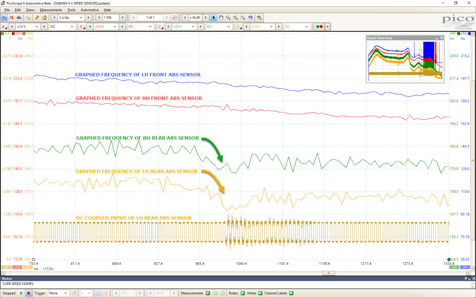
The waveform above monitors the square wave outputs from all four wheel speed sensors (front and rear) while driving over the speed humps. Each channel has been hidden from view except Channel D (yellow), where the square wave output can still be seen. To hide a channel from view, right-click anywhere on the scope screen and deselect the boxes adjacent to the channel letter you wish to hide. This removes clutter when adding math channels and assists with signal analysis.

In order to graph the frequency of each wheel speed sensor, a frequency math channel was created from the Tools tab, allowing for close analysis of the change in the wheel frequency as the car was driven over the speed humps. To create a frequency math channel, open the Math Channel Wizard by clicking on Tools > Math Channels > Create > Next > Advanced > freq followed by the channel letter (A, B, C or D) you wish to graph. Follow the Math Channel Wizard to completion by selecting a color and range for your math channel. To easily recognize your created math channel, select a color to match the channel input to be graphed (e.g. Channel A frequency math channel blue, Channel B frequency math channel red etc.).
It became apparent that there was a sudden drop in the frequency of the rear wheels when they rolled over speed humps, unlike the front wheels whose frequency decreased progressively. Math Channels C and D (below) confirm a rear-wheel frequency drop of 15 Hz within 30 ms, which fits perfectly with the symptom observed. Such a drop in wheel frequency will most certainly trigger the ABS into action.
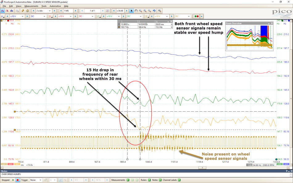
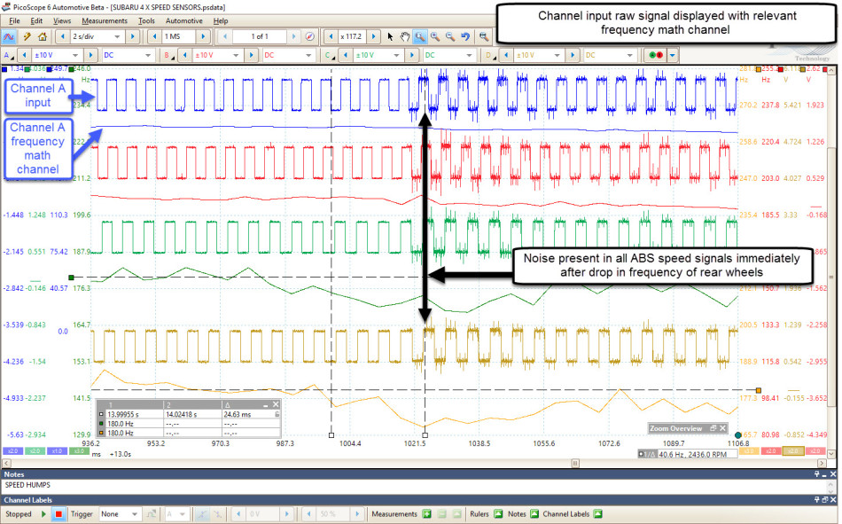
In addition to the frequency drop, there was noise present on the raw signal from the wheel speed sensors (indicated above on Channel D).
Could the detected noise be responsible for the sudden drop in the rear wheel frequency? Closer inspection revealed that the noise was present in all wheel speed signals immediately after the drop in rear wheel frequency and not before.
The manufacturer’s description of operation was referenced for in-depth knowledge of component functions. This knowledge is imperative when diagnosing any system and highlights the need for continual research and training.
Possible causes:
(Based on symptom and non-intrusive evaluations made above)
The action plan:
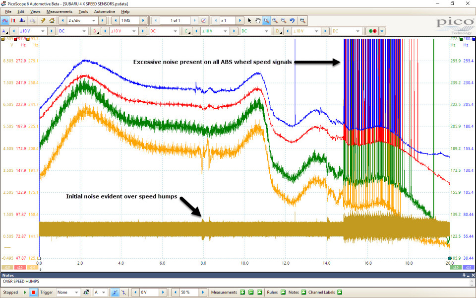
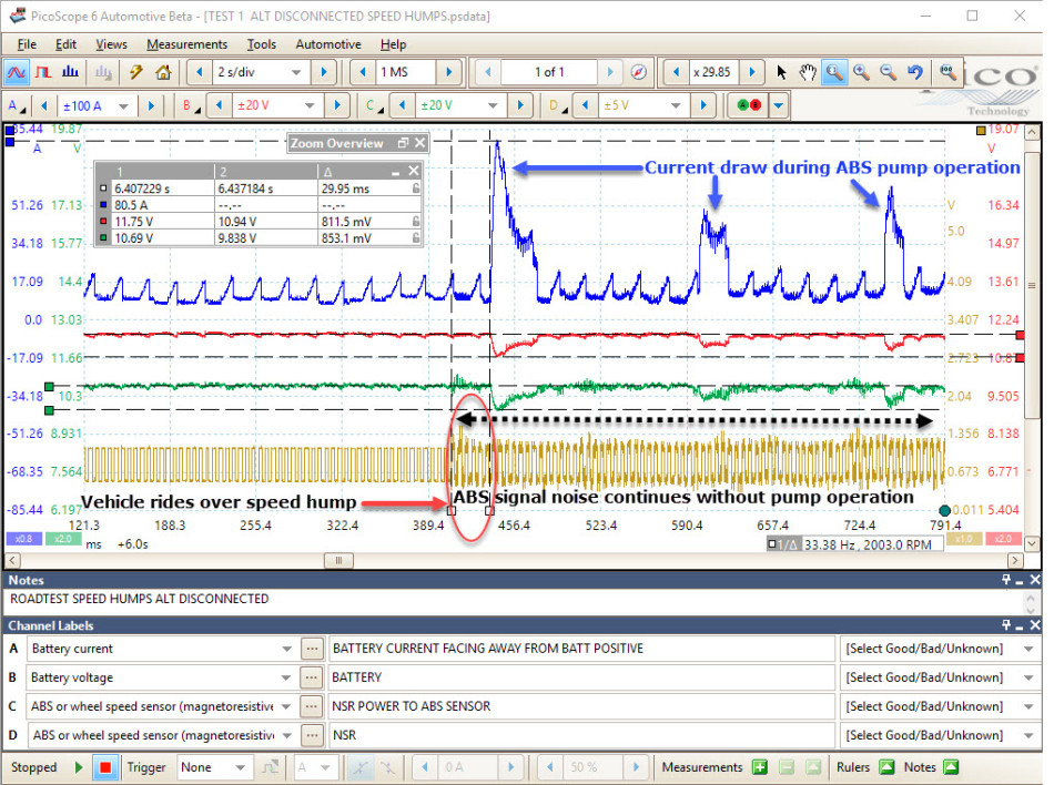
The plan is based on the initial evaluation, experience, and accessibility. Given that the ABS wheel speed sensors were, at least, recording wheel speeds, the noise present in the wheel speed signals became the focus of attention. The level of noise on the ABS speed signals can only be appreciated when viewed without the zoom feature. Could the noise actually be responsible for the ABS operation or vice versa?
Given that the noise was only apparent during ABS operation, the focus of attention moved to the current flow and the power supply to the ABS pump. The alternator was disconnected during a road test to limit the effect of the alternator compensation during battery loading via the ABS pump (revealing true battery load).
The results were quite astonishing as the ABS pump current peaked at 80 A while battery and ABS sensor supply voltages fell to approximately 11 V and 10 V respectively. Once again, the ABS speed signal became distorted, not only prior to the ABS pump operation but continually as the ABS pump motor was cycled. To confuse the issue further, rather than monitoring just the ABS speed signal voltage, I also measured the ABS sensor speed signal current (with the alternator connected). This revealed minimal noise and zero distortion contradicting all previous tests.

At this stage, it is time to recap and summarize what we know and don’t know so far.
I have to say that at this point, this vehicle nearly forced me into submission, as I could pinpoint areas of concern but could not establish a cause. As the saying goes “a problem shared is a problem halved”, so I turned to fellow users on the Pico Auto Forum.
Click on this link to see a demonstration of how help is always at hand and how Pico users are never short of ideas and suggestions.
Thank you to all who offered help as after numerous discussions, emails, and chats a real gem of information came to light. With reference to the noise evident on our wheel speed voltage signal, we looked at the ABS operation.
When the ABS control unit detects a rapid deceleration in wheel frequency, the potential for wheel lock-up is increased. As a direct response, the brake fluid pressure applied to the offending wheels is reduced during the pressure reduction phase of the ABS by rapid activation of the relevant ABS solenoid. This event takes place momentarily before the ABS pump operation and at repeated intervals during and after the pump operation. Remember, during imminent wheel lock-up, the pressure reduction phase takes priority, followed by the pressure hold phase and the pressure increase phase should the wheel begin to accelerate. (The ABS Pump operation delivers additional brake fluid pressure during the pressure increase phase).
The EMI/noise evident in our wheel speed voltage signal is a consequence of high-frequency switching of the ABS solenoids, resulting in the momentary collapse of a magnetic field in close proximity to the power/ground supplies of our wheel speed sensors (all of which reside inside the ABS control unit/actuator assembly).
Armed with the knowledge that the noise appears after the reduction in wheel speed and, more importantly, that the noise was not present in the wheel speed current signal, diagnostic efforts were diverted to actual wheel speeds (point three in the summary above).
In an attempt to discover more information about wheel speeds, I drove the vehicle for the first time (fault code erased prior to driving) at high speed (70 mph) while recording wheel speeds via serial data using a scan tool with superior Subaru coverage.
To my alarm, while maintaining a speedometer speed of 70 mph, the ABS warning light illuminated and the cruise control disengaged. Once again fault code “C0115- Wheel Speed Sensor” returned.
At this point in time, the recorded wheel speeds were saved for review to reveal a breakthrough in the diagnosis.
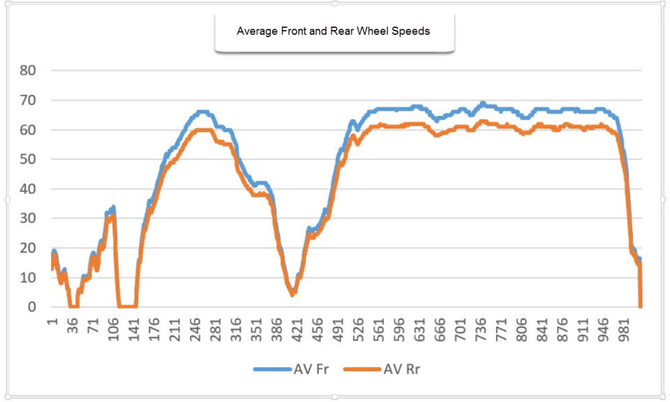
The graph above plots the average front and rear wheel speeds as captured during the total road test by the scan tool. We can clearly see a considerable difference in the front and rear wheel speeds, which seemed to increase in proportion to an increase in road speed.
To clarify, the higher the road speed the greater the difference between front and rear wheel speeds. At a speedometer reading of approximately 70 mph, the front road wheels recorded 68 mph while the rear wheel speeds report 62 mph, a difference of approximately 10% (using serial data).
How is this possible when wheels and tires are most certainly the same diameters? Could this be an ABS software error as the speedometer appears to read correctly for a given road speed?
(The speedometer receives road speed data from the ABS control unit via the CAN).
Once again further discussions took place. The suggestion was made to count the number of teeth on each ABS pick-up ring (front and rear). This is easier said than done, as we are not looking at a conventional toothed pick-up ring. Instead, we have an alternate pole (north/south) magnetic pick-up ring integrated into the wheel bearing/hub assembly.
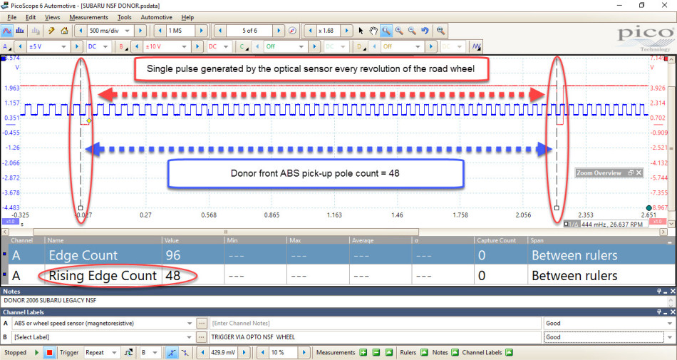
The least intrusive way to determine the pole count was by far to use the Pico optical sensor kit in conjunction with reflective tape placed at a strategic point on the surface of the road wheel. The reflective tape generates a single pulse from the optical sensor to denote one revolution of the road wheel. The pulses from the ABS sensor were counted between the optical sensor pulses to reveal the pole count.

Rotating the road wheels by hand generates a single pulse from the optical sensor every revolution of the road wheel. With the ignition on, the ABS wheel speed sensors will generate pulses relative to wheel speed. By using the Time Rulers to align with the pulses from the optical sensor, we can clearly identify a single revolution of the road wheel.
Rather than physically counting the pulses from the wheel speed sensor, we can use the Edge Count feature under the Measurement tab.
To create an Edge Count measurement, click on Measurements > Add Measurement > Select the Channel to measure (A) > Select the measurement type (Edge Count) > Choose the section of the waveform to be measured (between rulers).
Remember, Edge Count will count both the rising and falling edges of the signal between the rulers on channel A. To obtain just the pole count we can use either the Rising edge count or the Falling edge count on channel A.

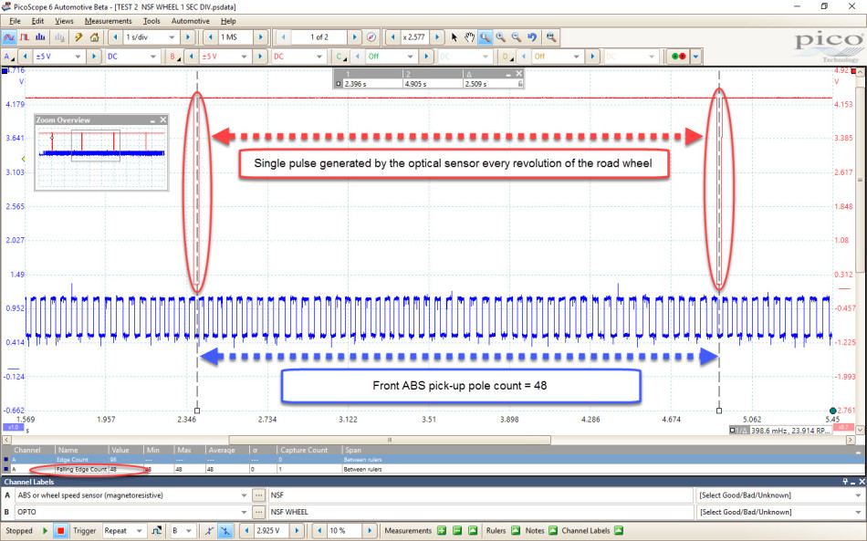
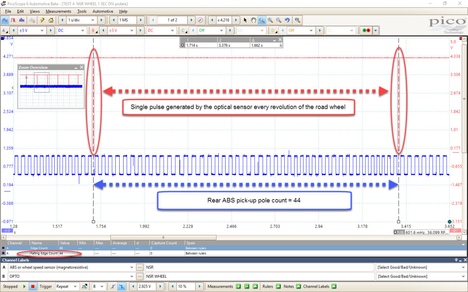
As you can see in the waveforms above, we have a different pole count between the front and rear road wheels. (48 poles front, 44 poles rear) This most certainly explains the differing wheel speeds and the inadvertent operation of the ABS when driving over speed humps.
Now we were faced with another problem, which wheel has the incorrect pole count? Or another scenario, are the pole counts correct but the ABS control unit configured incorrectly? If the ABS control unit can be configured for a variety of vehicles (and I believe it can) it looks like we either have the incorrect software or the incorrect ABS control unit. The ABS control unit did, however, look like the original.
My assumption led me to believe the front wheel speeds were correct based on the speedometer reading. At 70 mph the front ABS sensors were reading approximately 67-68 mph which is the kind of deliberate error we see with speedometers, whereas the rear wheels were reporting an uncharacteristic erroneous lower speed of 62 mph. A non-intrusive test here would have been a 3rd party GPS device (Sat Nav / smartphone) placed on the fascia to obtain the true road speed, but once again lady luck shone my way.
Thanks to the forum post, I received a call from Kevin at Ives Garage telling me that a Subaru Legacy had been delivered for an MOT. I was over there faster than you can say "Subaru" to carry out the optical sensor test (ABS pole count) using the procedure mentioned above. The waveforms below reveal both front and rear ABS pole counts to be 48.

This then led me full circle back to the customer interview where it was mentioned that a wheel bearing had been replaced (information I chose to omit at my own peril). The initial customer interview mentioned a replacement wheel bearing to the right rear only, however, additional questioning revealed that the customer had purchased four new wheel bearing/hub assemblies from a famous internet auction site and that both the rear wheel bearing/hub assemblies had been replaced.
The original rear wheel bearings had been discarded, however, the new front wheel bearings from the same set as the rear bearings were inspected to determine the pole count. I used a beautifully simple but effective Magnetic Field Finder.

Using the magnetic field finder allowed for another non-intrusive pole count which confirmed 44 teeth, matching the installed rear bearing/hub assemblies. Had all 4 wheel bearings been installed together, no ABS fault would have occurred and a speedometer error of approximately 10% would have ensued.
Armed with this information, we decided to replace the rear wheel bearing/hub assemblies again, using the correct specification bearing with the relevant pole count of 48. These were most certainly checked before the installation with the Magnetic Field Finder to count the number of poles.
The captured serial data below (after fix) reveals how the line graph thickness had to be increased in order to distinguish the front and rear wheel speeds given that both speeds were now identical. The waveform below demonstrates the same graphing feature using math channels in PicoScope.
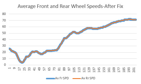
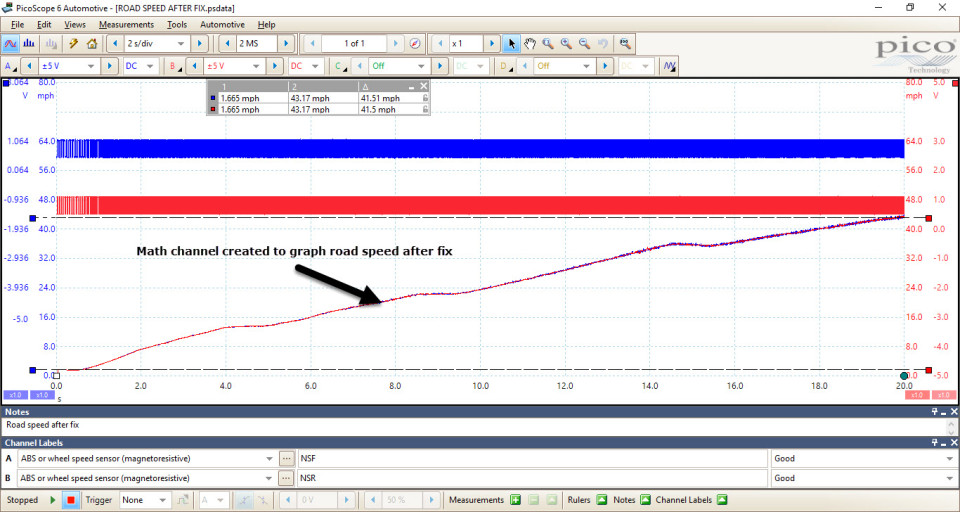
Using a math channel to calculate road speed from an ABS wheel speed signal could be very useful in the future for those faced with such diagnosis, or for those who wish to qualify vehicle speeds against serial data.
When using a tire size of 215/45/17 and an ABS pole/tooth count of 48, we require:
The formula for wheel speed in mph is written:
Wheel/tire speed (frequency Hz x 60 = RPM) x tire circumference (meters) = meters per minute
Meters per minute x 60 = meters per hour
Meters per minute / 1000 = kilometres per hour
Kilometres per hour x 0.621371 = miles per hour
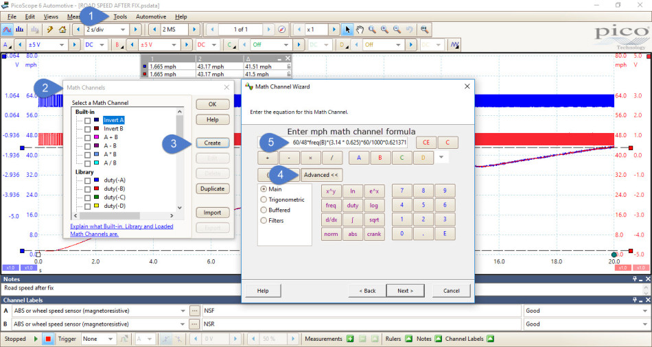
Math channel formula required to calculate mph from the wheel speed signal on channel B:
60/48*freq(B)*(3.14 * 0.625)*60/1000*0.621371
To create an mph math channel for the wheel speed signal on channel B, open the math channel wizard by clicking on Tools > Math Channels > Create > Next > Advanced, and type in the formula above. Complete the Math Channel Wizard by selecting colour, measurement unit (mph), and range for your math channel. To recognize your created math channel, select a matching colour for the channel input to be graphed (e.g. Channel A frequency math channel Blue, Channel B frequency math channel Red etc.).
The image below highlights the math channel formula entry procedure.
Rear wheel bearing/hub assemblies (with a pole count of 48).
Looking back over this case study, I do wonder if I could have tackled this differently in order to speed up the diagnostic process (hindsight is a wonderful thing).
From my perspective, a huge thank you goes to Charles Figgins at Bilstein Group, Kevin Ives at Ives Garage, Mark Stammers, Gary Burgess, everyone who contributed on the Pico Auto forum.
Joe Gartner
May 01 2017
Steve:
Thanks for the excellent write-up!
Just curious if you could mention where you got the magnetic field finder. I’m going to add it to my diagnostic tool kit.
Thanks again for the great article!
Regards,
-Joe Gartner
Ian Petersen
April 29 2017
A fascinating and very interesting detective story.
Well done & thanks, Steve.
Just curious: why is the US spelling ‘tire’ used in the Case Study but the UK spelling ‘tyre’ used on the Forum?
Ian (Australia)
Harrythecargeek
April 28 2017
Always check the basics, how were the battery terminals in this car? I bet they were highly corroded, also bet the ground terminals were highly oxidized.
Nice job.
horstp
April 28 2017
A lot of new information. This shows how nearly perfect the software of PicoScope6 Automotive has become, and what unimagined possibilities it opens up to the user.
Ken Pickerill
April 27 2017
Interesting post, well researched. Thanks for sharing!
Rob Nicholson
April 03 2017
Interesting read and good result.


