PicoScope 7 Automotive
Available for Windows, Mac, and Linux, the next evolution of our diagnostic scope software is now available.
Automotive guided tests
Library of examples on how to perform tests when using PicoScope.

Training
Our collection of training videos, articles, guides and information on training courses.

Waveform library
The Waveform Library is a global database of waveforms uploaded by PicoScope users.

Case studies
Real-life case studies show how the professionals use PicoScope to diagnose vehicle faults.

A to Z of PicoScope
Detailed description of various PicoScope software and hardware features.

Videos
Training resources and demonstrations on PicoScope and the Automotive Diagnostics Kit.

Newsletter
Archive of our monthly Automotive Newsletters.

Documentation
Download manuals, brochures, posters, and training materials.

Reviews and awards
Accolades for the preferred diagnostic tool for service centers and vehicle manufacturers.

Ignition systems have two circuits that result in a spark being fired at the end of a spark plug. The primary circuit is between the battery and the ignition coil. The secondary circuit is between the ignition coil and the spark plug.
A secondary ignition circuit consists of three components and is the basis for newer variations of the ignition system. The three components are:
Over the years, secondary ignition systems have changed, mainly to make the systems more reliable, durable and adjustable to suit the needs of modern engines. These days you can get both electronic ignition systems and distributorless ignition systems.
The electronic system has an ECM controlling the opening and closing of the primary circuit. This means that the cam in the distributor, which often wears out, can be removed. These systems create a stronger spark.
The distributorless ignition systems benefit from not having moving parts, which removes common issues like engine drag because of the distributor’s bulkiness, timing adjustments or starting problems due to moisture in the distributor. These systems replace the distributor with an ECM, an ignition control module and a magnetic triggering device that opens and closes the circuit. The current is sent to coils connected to one or two spark plugs and the timing is controlled.
Problems in the secondary circuit could cause issues with the ignition (problems in the primary circuit or the fuel injection system could also affect the ignition). It is necessary to use an oscilloscope and a secondary pick-up probe to confirm problems in the secondary circuit. Remember that the secondary circuit has high-voltage current running through it, so keep safety guidelines in mind when working with this.
The signal below has become familiar to most technicians:
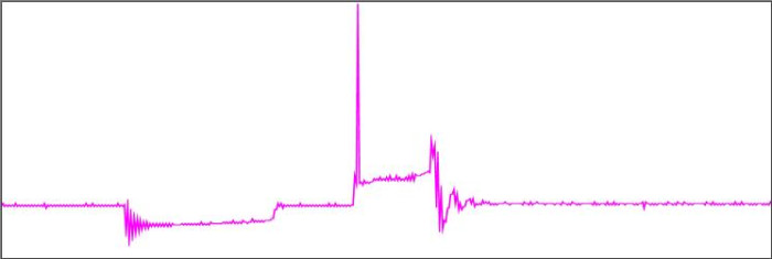
Pico Technology’s products and connections have been updated to follow the changes. We now use Ignition pick-up leads to connect to spark plug leads and coil extensions for multiple coil packs. In most modern vehicles, the new coil packs are placed directly on top of the spark plugs giving us the option to use the non-intrusive, flexible coil-on-plug (COP) probe.
It is important to understand the information you can read in the waveform, seeing the stages in the signal.
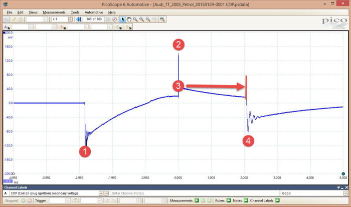
Some spark plug intervals have become longer, from 20,000 miles to 120,000 miles. This could lead to other components failing in different systems. It is fast and easy to test the system with the Coil-On-Plug probe.
We recently did some testing on spark plugs with different gaps in the same engine, to see the difference that smaller or larger gaps make.
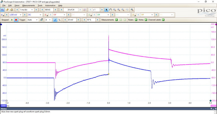
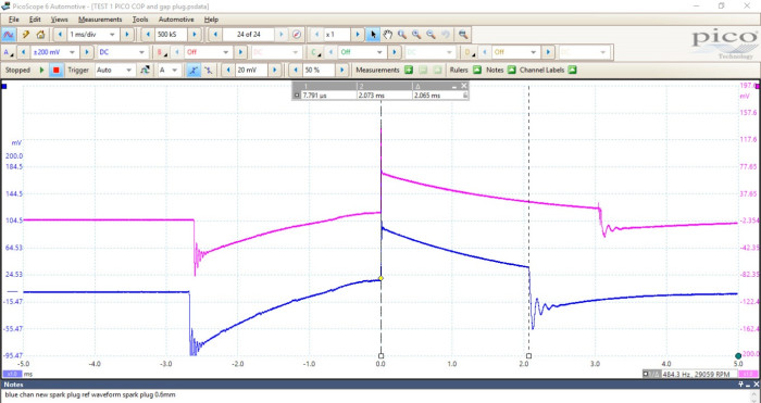

Above are waveforms with a new spark plug with a gap of 0.8 mm (blue) and a new spark plug with a gap of 0.6 mm (magenta). The difference between the two burn times is 0.99 ms.
Most manufacturers do not give any data on their ignition systems or spark plug operation, so capturing your own data is valuable.
James Allen Wiger
May 21 2020 - 9:51:42
What scope tool and display are needed for these kinds of traces?


