PicoScope 7 Automotive
Available for Windows, Mac, and Linux, the next evolution of our diagnostic scope software is now available.
Automotive guided tests
Library of examples on how to perform tests when using PicoScope.

Training
Our collection of training videos, articles, guides and information on training courses.

Waveform library
The Waveform Library is a global database of waveforms uploaded by PicoScope users.

Case studies
Real-life case studies show how the professionals use PicoScope to diagnose vehicle faults.

A to Z of PicoScope
Detailed description of various PicoScope software and hardware features.

Videos
Training resources and demonstrations on PicoScope and the Automotive Diagnostics Kit.

Newsletter
Archive of our monthly Automotive Newsletters.

Documentation
Download manuals, brochures, posters, and training materials.

Reviews and awards
Accolades for the preferred diagnostic tool for service centers and vehicle manufacturers.


20 A / 60 A DC (low amps) current clamp

Multimeter Probes

Back-pinning Probe Set

Flexible Back-pinning Probe

Large Dolphin/Gator Clips
*At Pico we are always looking to improve our products. The tools used in this guided test may have been superseded and the products above are our latest versions used to diagnose the fault documented in this case study.
The purpose of this test is to examine the output signal and heater current waveforms from a Pre-Catalytic Convertor Zirconia type lambda sensor.

View connection guidance notes.
Note
The orientation of the current clamp relative to the wire will determine whether it has a positive or negative output. If a live waveform does not appear on your screen, or appears to be inverted, try reversing the orientation of the clamp.
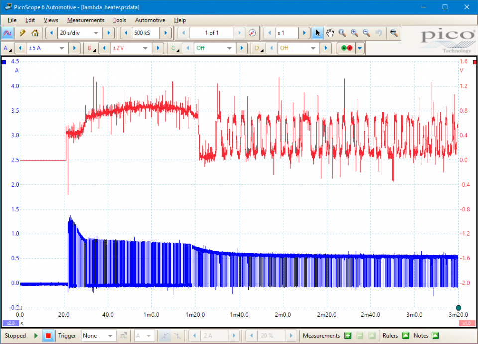
This shows the current in the heater element, which is a pulse width modulation (PWM) or square wave type signal. The pulses of current start with a height of about 1.3 amps and then decline to about 0.5 amps. This is due to the increase in the heater's resistance as it warms up. The voltage across the heater is a constant battery voltage from the ECM, so as the heater's resistance rises, the current will drop.
The most important feature of this waveform is not the height of the current pulses but their width. The ECM in this engine outputs a pulse of current every half a second (500 ms), and adjusts the width of each pulse to control the heater power. It is difficult to see the individual pulses in the waveform above, so we need to zoom in using the zoom tools  . The magnified view is shown here on the right:
In the waveform above, we have zoomed in to the 20-second interval just after switch-on. We have also placed a couple of rulers at about 26 and 30 seconds after switch-on, and set PicoScope to display the average current over that interval. PicoScope shows that the average current between the rulers is about 860 mA. This tells us that the pulsed current fed to the heater has the same effect as a constant current of about 860 mA.
After the 30-second point, the current pulses get narrower. If we moved the rulers into that region, PicoScope would tell us that the average current there is about 185 mA, or about 20% of the peak current. The output of the heater would therefore be lower.
This shows the voltage signal from the sensor, representing the oxygen content of the exhaust gas. PicoScope has been set up to filter the signal to remove noise spikes.
Go to the drop-down menu bar at the lower left corner of the Waveform Library window and select, Oxygen / O2/ Lambda heater current.


For technical information on the sensor itself, see the Zirconia lambda sensors topic.
The purpose of the heater element is to heat the lambda sensor up to the start of its 250 to 950 °C operating range as quickly as possible. At this point the fuel injection system will change from open-loop to closed-loop fuel control. This cannot occur until there is a switching signal from the lambda sensor output wire, informing the engine ECM of the oxygen content of the exhaust system. It is imperative that the system moves to closed-loop control as quickly as possible to meet stringent emission system regulations. Any defects in the heater element system will reduce the lambda sensor switching rate and invariably bring on the engine emissions malfunction warning lamp.
If the element is not drawing any current, check that there is a normal battery voltage supply on one of the connecting wires and the ECM is attempting to intermittently switch the other wire to earth. If there is no earth switching then also check the continuity of the wire back to the ECM for an open circuit.
The element's resistor can also be checked across the two white wires. On our test vehicle the element had a resistance of 6 Ω. Check the manufacturer's data for the vehicle under test.
Typically the four wires on the Zirconia lambda sensor are:
or:
This is only a guide and may vary with different manufacturers.
If the lambda sensor is removed and then refitted or replaced then it is also worth checking the correct torque setting. On our test vehicle the correct tightening torque was 45 Nm.
GT142-2
Disclaimer
This help topic is subject to changes without notification. The information within is carefully checked and considered to be correct. This information is an example of our investigations and findings and is not a definitive procedure.
Pico Technology accepts no responsibility for inaccuracies. Each vehicle may be different and require unique test
settings.
We know that our PicoScope users are clever and creative and we’d love to receive your ideas for improvement on this test. Click the Add comment button to leave your feedback.


